There are many different types of placement machines (also called pick and place machines) on the market, the goal of which is to place electronic components on the PCB surface mount as accurately and quickly as possible.
With the increase in the types of electronic components available, the functions of these machines have also increased. Some machines are specifically designed for speed, while others pay more attention to flexibility. Therefore, it is very important to choose a placement machine according to the product type. important.
Machines designed to increase speed are often referred to as "ultra-high-speed placement machines", which can achieve parts placement speeds of up to 100,000 cph (parts per hour). The flexible placer can handle connectors ranging from 01005 to 150mm, and has the ability to inspect/place micro-BGA (ball grid array) and PoP (package-on-package) devices.
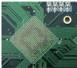
The general concept is to send the PCB printed with solder paste into the placement machine, and then transport it to the placement area through a conveyor belt and clamp it. Then, the machine's vision system uses the fiducial mark to confirm the fixed position of the PCB and initiate the electronic component placement program.

The component placement process involves using nozzles in turn to pick up each component from the feeder and transport it to the programmed location.
Each type of placement machine has its own program format, but all contain the same information, including-part number, circuit board reference, rotation, packaging information and X/Y position.
After the assembly is completed, the components are loosened and transported to the next workbench in the production line via a conveyor belt
In order to achieve reliability of the placement machine, the following points need to be considered:
· PCB design
1. Panel size
2. Treatment belt
3. Fiducial Mark
4. Component size and location
· Nozzle
· visual system
· PCB support
· How to provide components
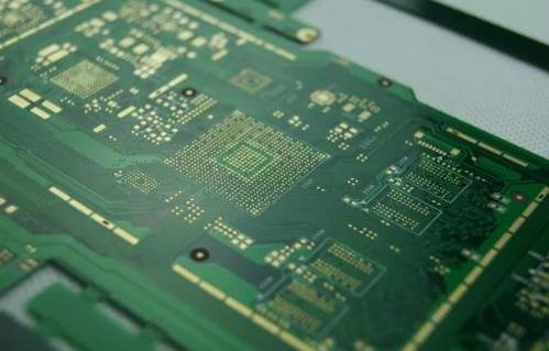
PCB design
The design of the PCB and the way the PCB is paneled will have an impact on the component placement process. The following is a list of considerations:
· Panel size-All machines have a specified maximum and minimum panel size that can be processed.
· Handling tape-It is very common when designing a PCB to place the components close to the edge. Therefore, due to the PCB handling mechanism in various machines, it is very important to panelize the PCB.
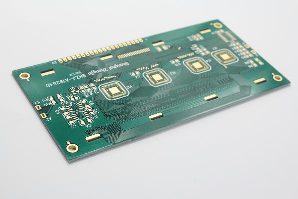
· Fiducial marks-fiducial marks are simple shapes within the PCB trace layer, and the positions of these shapes should not be confused with other aspects of the circuit board design
The placement machine vision system uses fiducial marks to ensure that all components are correctly positioned. It is recommended to use the farthest reference point when aligning the PCB to the machine to achieve maximum accuracy, and it is recommended to use three reference points to determine whether the PCB has been loaded correctly.
· Component size and location-a large population design may place smaller components close to larger components, and these components need to be considered when generating the placement program. All the smaller components need to be placed before the larger ones to ensure that they will not be disturbed-placement program optimization software usually takes this into account.
Nozzle
As the number of surface mount components available on the market continues to increase, there are also many different types of nozzles available. Most nozzles use vacuum to hold the component firmly between the pick and place steps, but this does rely on the component having a flat top surface. The alternative is a gripper nozzle that grips the side of the assembly and uses vacuum to actuate the mechanism.
It is possible to specify that the top of certain parts (such as connectors) is not flat, and can be purchased from a supplier using pads/inserts that can be vacuum picked and placed.
It is very important to choose the correct nozzle for each different part to be placed to ensure accurate and consistent placement-choose the following
It is important to check the nozzle regularly for problems, such as solder paste contamination, as shown below. During pick and place, this can cause components to stick to the nozzle and cause defects such as missing or misplaced parts
visual system
Before placement, the machine vision system analyzes each component picked to ensure that all programmed parts match in size and check for damage, such as bent leads. It is important to program each component with the correct tolerance parameters so that the machine can determine if incorrect parts are loaded, and also not to reject acceptable parts
PCB support
Most PCBs are made of fairly rigid 1.6mm FR4 material, but when thinner materials are used or there are slots, the support of the PCB will be a challenge. During component placement, this can lead to inconsistent results because there will always be a certain amount of placement pressure-if the PCB is not fully supported, it will flex. Setting up support can be time consuming, so you can see many adaptive systems available here. The flexible support system can not only be set up quickly, but they should also be taken into consideration if the bifacial module is to be constructed with the module already installed on the underside. Below you can see the two most common solutions, which mold themselves around the placed components
How to provide components
Surface mount components are provided in a variety of ways, the most common being tape/reel, pipe and tray. All machine manufacturers have feeders for this type of packaging, but problems can arise when only a few parts are needed for small batch assembly. In this case, the components are usually provided in a way that cannot be loaded directly onto the machine, so they are either sent away to be placed in the aforementioned packaging or placed manually-neither of which is ideal because they are expensive, time-consuming and time-consuming. Costly. Quality issues.
For components provided in the form of tape, if only a small amount is required, there are many available "short belt" feeding methods that can be loaded as pallets.