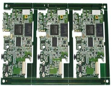
SMT patch refers to the abbreviation of a series of technological processes that are processed on the basis of PCB, and PCB (Printed Circuit Board) is a printed circuit board. SMT is surface mount technology (Surface Mounted Technology) (abbreviation for Surface Mounted Technology), and it is the most popular technology and process in the electronics assembly industry.
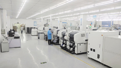
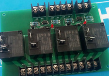
SMT placement machines are commonly known as surface mount technology. They are generally used to mount electronic components on PCB boards, as well as LED lamp beads and SMT components. They are used in SMT production lines to speed up production efficiency and replace labor cost-saving equipment.

The entire SMT production line consists of three processes: screen printing, component placement and reflow soldering. Mounting is an important part of the entire surface mount process. Therefore, the smt placement machine is the largest investment in the entire smt production line and the most in production. The key and most complex equipment.
The placement machine is actually a kind of precision industrial robot, which is a complex of machine-electricity-optical and computer control technology. Through functions such as absorption-displacement-positioning-placement, without damaging the components and the printed circuit board, it can quickly and accurately mount the SMC/SMD components to the specified pad positions on the PCB board. There are three methods for component alignment: mechanical alignment, laser alignment, and visual alignment.
The placement machine is composed of a frame, xy motion mechanism (ball screw, linear guide, drive motor), placement head, component feeder, PCB bearing mechanism, component centering detection device, and computer control system. The movement is mainly realized by the xy motion mechanism, the power is transmitted by the ball screw, and the directional motion is realized by the rolling linear guide motion pair. Such a transmission form not only has small motion resistance, compact structure, and high motion accuracy. Ensure the placement accuracy of each component.
The placement machine is marked with Mark on important components such as the placement spindle, moving/static lens, nozzle holder, and feeder. Machine vision can automatically calculate these Mark center system coordinates, establish the conversion relationship between the placement machine system coordinate system and the PCB and placement component coordinate system, and calculate the precise coordinates of the placement machine movement; the placement head is based on the imported Place the package type, component number and other parameters of the component to the corresponding position to grab the nozzle and suck the component.
The static lens detects, recognizes and aligns the picking components according to the visual processing program; after the alignment is completed, the placement head mounts the components to the predetermined position on the PCB. This series of component recognition, centering, inspection and placement actions are all instructed and automatically completed by the control system after the industrial computer obtains the relevant data according to the corresponding instructions.