In order to improve the straight-through rate of PCBAproducts, in addition to reducing the solder joint defects that are visible to the naked eye, it is also necessary to overcome invisible defects such as virtual soldering, poor bonding strength of the solder interface, and large internal stress in the solder joints. Therefore, the reflow soldering process must be Under controlled conditions. The reflow soldering process requirements are as follows:
(1) According to the temperature curve of the solder paste used and the specific conditions of the PCB, combined with the soldering theory, set an ideal reflow soldering temperature curve, and regularly test the real-time temperature curve to ensure the quality and process stability of the reflow soldering.
(2) The welding should be carried out in accordance with the welding direction of the PCB design.
(3) During the welding process, strictly prevent the conveyor belt from vibration.
(4) After welding, the welding effect of the first printed board must be checked. Check whether the soldering is sufficient, whether there are traces of insufficient solder paste melting, whether the surface of the solder joint is smooth, whether the shape of the solder joint is half meniscus, the condition of solder balls and residues, bridges and virtual soldering, but also check The change of PCB surface color, after reflow, allow a little but even discoloration of the PCB, and adjust the temperature curve according to the inspection results. The welding quality should be checked regularly during the whole batch production process.
Reflow soldering is to design a temperature profile (Temperature Profile) to allow the product to increase and decrease temperature along the designed curve to achieve the purpose of soldering and curing. The temperature profile is a function of the temperature and time applied to the circuit board. When drawing with the Cartesian plane, any given time during the reflow process represents a curve formed by the temperature of a specific point on the PCB. In the printed circuit board assembly using surface mount components, to obtain high-quality solder joints, an optimized reflow temperature curve is one of the most important factors.
1) Basis for setting the reflux temperature curve
(1) Set according to the temperature profile of the solder paste. Solder pastes with different metal content have different temperature curves, which should be set according to the temperature curve provided by the solder paste supplier (mainly controlling the heating rate, peak temperature and reflow time).

(2) Set according to PCB material, thickness, multi-layer board, size, etc.
(3) Set according to the assembly density of the components, the size of the components and whether there are special components such as BGA.CSP.
(4) Set according to the specific conditions of the equipment, such as the length of the heating zone, the heating source material, the structure of the reflow furnace, and the heat conduction method.
(5) Determine the set temperature of each temperature zone according to the actual location of the temperature sensor in the heating zone. If the temperature sensor is located inside the heating element, the set temperature is about 1 times higher than the actual temperature; if the sensor is located at the top or bottom of the furnace cavity, the set temperature can be about 30 higher than the actual temperature.
(6) Set according to the size of the exhaust air volume. Generally, reflow ovens have specific requirements for the exhaust air volume, but the actual exhaust air volume sometimes changes due to various reasons. When determining the temperature curve of a product, the exhaust air volume should be considered and measured regularly.
(7) The ambient temperature also affects the furnace temperature. Especially for the reflow furnace with a short heating temperature zone and narrow furnace body width, the furnace temperature is greatly affected by the ambient temperature, so avoid convective air at the inlet and outlet of the reflow furnace.
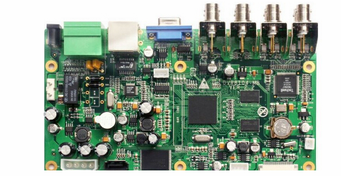
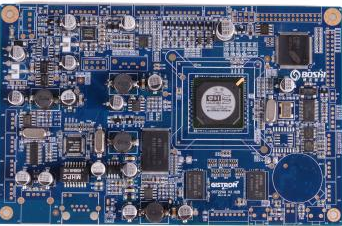
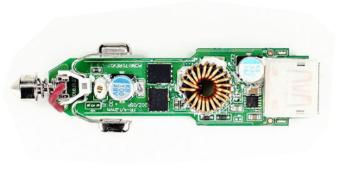
Smart motherboard chip processing
The most critical parameters that affect the shape of the temperature curve are the speed of the conveyor belt and the temperature setting of each zone. The belt speed determines the duration of exposure of the substrate to the temperature set in each zone. Increasing the duration can make the temperature on the circuit close to the temperature setting of that zone. The total duration of each zone determines the total soldering time; the temperature setting of each zone affects the temperature rise rate of the PCB, and increasing the set temperature of the zone allows the substrate to reach a given temperature faster.
(1) Test tools: temperature curve tester, thermocouple.
Many reflow ovens now have thermometers. Thermometers are generally divided into two categories: real-time thermometers, which instantly transmit temperature-time data and make graphs; the other kind of thermometers sample and store data, and then upload them to the computer.
The thermocouple must be long enough and able to withstand the typical furnace temperature.
The information contained in the solder paste characteristic parameter table is critical to the temperature profile, such as the duration of the temperature profile, the active temperature of the solder paste, the melting point of the alloy, and the maximum reflow temperature.
(2) Position and fixation of thermocouple:
1. Attach the thermocouple of the temperature curve tester to 3 to 6 test points selected on the SMA board. The selection of test points is determined by the point with the largest heat absorption and the point with the smallest heat absorption, and their temperature represents the welding temperature on the SMA board.
2. The better way to fix the thermocouple is to use high temperature solder, such as silver-tin alloy, with the solder joints as small as possible. In addition, you can use a small amount of thermal compound (also called thermal grease or thermal grease) spots to cover the thermocouple, and then stick it with high temperature tape. Another method is to use high-temperature glue to attach the thermocouple, such as a cyanoacrylate binder. This method is usually not as reliable as other methods.
(3) Steps to determine the reflux temperature curve: Before the test starts, it is necessary to have a basic understanding of the ideal temperature curve. Theoretically ideal curve consists of 4 parts or intervals, the first 3 zones are heated and the last zone is cooled. The more temperature zones of the reflow oven, the more accurate and close the profile of the temperature curve can be.
1. Set the speed of the conveyor belt: this setting will determine the time spent by the PCB in the heating channel. Typical solder paste parameters require a heating curve of 3 to 4 minutes. Dividing the total heating channel length by the total heating temperature sensing time is the accurate conveyor speed.
2. Set the temperature of each temperature zone: the displayed temperature only represents the temperature of the thermocouple in the zone. If the thermocouple is close to the heating source, the displayed temperature will be higher than the temperature in this zone; the closer the thermocouple is to the direct channel of the PCB, the displayed temperature will be The more it can react to the temperature of the interval. Therefore, before setting the temperature of each temperature zone, you should first consult the manufacturer to understand the relationship between the displayed temperature and the actual temperature.
3. When the machine is started and the furnace is stable (all the actual displayed temperature is equal to the set temperature), the curve starts: Put the connected thermocouple and the PCB of the temperature curve tester into the conveyor belt, and trigger the thermometer to start recording data. For convenience, some thermometers, including a trigger function, automatically start the thermometer at a relatively low temperature, which is slightly higher than the human body temperature of 37 °C (98.6 F.). For example, the automatic trigger of 38 dragons (100 F.) allows the thermometer to start working almost as soon as the PCB is placed in the conveyor belt and into the furnace, so that the thermocouple does not trigger falsely when it is in the human hand.
4. After the initial temperature curve is generated, compare it with the curve inferred by the solder paste supplier: First, it must be verified that the total time from the ambient temperature to the reflow peak temperature is in harmony with the desired heating curve time. If it is too long, proportionally Increase the speed of the conveyor belt; if it is too short, the opposite is true.
5. Compare the measured temperature curve shape with the desired shape and adjust it. When adjusting, the deviation from left to right (process sequence) should be considered. For example, if there is a difference in the preheating and recirculation zones, first adjust the difference in the preheating zone correctly. It is generally best to adjust one parameter at a time and run this curve setting before making further adjustments. This is because a change in a given zone will also affect the results of subsequent zones.
6. When the final graph matches the desired graph as much as possible, record or store the parameters of the furnace for later use.