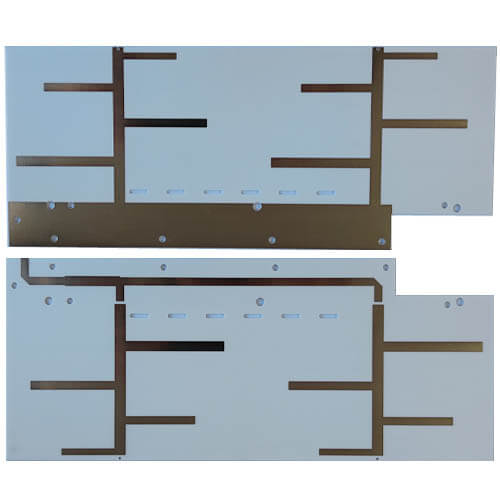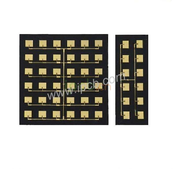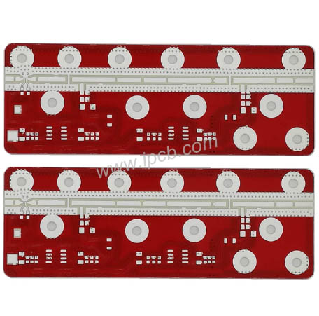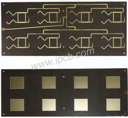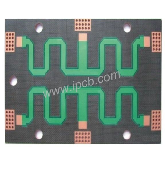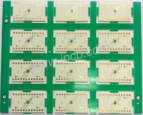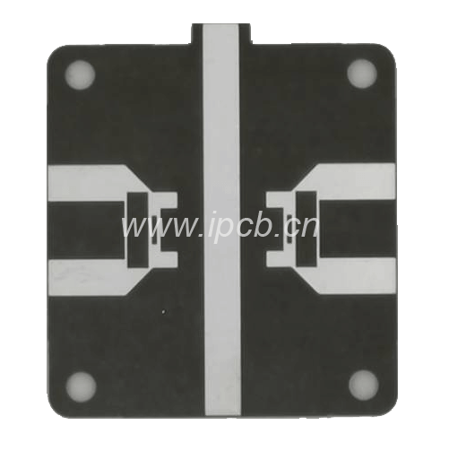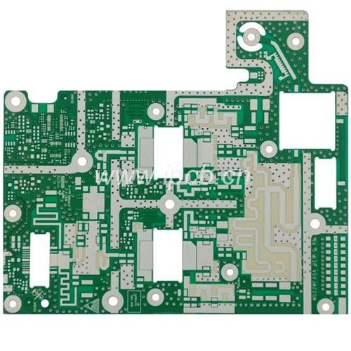


Product: RF PCB
Material: FR-4, Teflon, PTFE, Ceramic, Hydrocarbon
Quality standard: IPC Class2, Class3
PCB DK: 2.0 -1.6
Layers: 1-2 Layer, Multilayer PCB
Thickness: 0.254mm - 12mm
Copper thickness: 0.5oz - 2oz
Surface technology: Silver, Gold, OSP
Features: Strict tolerance control of RF circuits
Application: Antenna, instrument, Equipment
Material Selection of RF PCB
PCB materials include organic and inorganic materials. The most important property of RF PCB materials is the dielectric constant ε r. Dissipation factor (or dielectric loss) tan δ, Thermal expansion coefficient CET and moisture absorption rate. among ε R affects circuit impedance and signal transmission rate. For RF circuits, the dielectric constant is the most important factor to be considered.
IPCB company has rich manufacturing experience in RF circuit PCB and can produce RF PCB qualified. For the selection of RF materials, please click - RF PCB material
Characteristics of RF PCB
- A wider range of permittivity, from permittivity 2.0-16
- Lower loss
- More accurate impedance control
- More accurate RF circuit tolerance, minimum tolerance of IPCB is ± 0.02mm
- More stringent thickness control

RF circuit design
As the frequency increases, the wavelength of the corresponding electromagnetic wave becomes comparable to the size of discrete components, and the electrical response of resistance, capacitance, and inductance will begin to deviate from their ideal frequency characteristics. At this time, the common PCB is no longer applicable, and the RF PCB needs to be used.
Main components of RF circuit: RF transmission line, filter, power amplifier, mixer, oscillator and RF PCB circuit board.
Precautions for RF circuit design
1. Interference between digital circuit module and analog circuit module
If the analog circuit is RF And digital circuits work independently and may work well respectively. However, once they are placed on the same circuit board and work together with the same power supply, the whole system is likely to be unstable. This is mainly because the digital signal frequently swings between the ground and the positive power supply>3 V. The period is very short, usually nanoseconds. Because of the large amplitude and short switching time. So that these digital signals contain a large number of high-frequency components independent of the switching frequency. In the analog part, the signal transmitted from the wireless tuning loop to the wireless device receiving part is generally less than l μ V。 Therefore, the difference between the digital signal and the RF signal will reach 120 dB. obviously. If the digital signal can not be separated from the RF signal well. Weak RF signals may be damaged, so the working performance of wireless devices will deteriorate, or even cannot work at all.
2. Noise interference of power supply
RF circuit is very sensitive to power supply noise, especially to burr voltage and other high-frequency harmonics. The microcontroller will suddenly absorb most of the current in a short time within each internal clock cycle because modern microcontrollers are made with CMOS technology. So. Suppose a microcontroller operates at the internal clock frequency of 1MHz, and it will extract current from the power supply at this frequency. If proper power decoupling is not adopted It will cause a voltage burr on the power line. If these voltage burrs reach the power supply pin of the RF part of the circuit, it may lead to work failure in serious cases.
3. Unreasonable ground wire
If the ground wire of the RF circuit is handled improperly, some strange phenomena may occur. For digital circuit design, most digital circuits perform well even without a ground layer. In the RF band, even a short ground wire can act as an inductor. Roughly calculated, the inductance per mm is about 1nH, and the inductance of the 10 Toni PCB circuit is about 27 Ω at 433 MHz. If the ground layer is not used, most of the ground wires will be longer, and the circuit will not have the designed characteristics.
4. Radiated interference of antenna to other analog circuits
In RF PCB circuit design, there are usually other analog circuits on the PCB. For example, many circuits have analog-to-digital conversion ADC Or DAC. The high-frequency signal sent by the antenna of the RF transmitter may reach the analog input file of the ADC, such as the elevator card information, and the email signal. If the processing of the ADC input terminal is unreasonable, the RF signal may self-excite in the ESD diode of the ADC input. This causes ADC deviation.
When designing an RF circuit layout, the following principles must be satisfied first
1. Try to turn the high-power RF amplifier HPA And low noise amplifier LNA Isolation, in short, is to keep the high-power RF transmitting circuit away from the low-power RF receiving circuit
2. Make sure that the high power area on the RF PCB has at least a whole ground, and there should be no via on it. Of course, the larger the copper foil area, the better
3. The decoupling of the RF circuit and power supply is also extremely important
4. RF output usually needs to be far away from the RF input
5. Sensitive analog signals should be as far away from high-speed digital signals and RF signals as possible
Product: RF PCB
Material: FR-4, Teflon, PTFE, Ceramic, Hydrocarbon
Quality standard: IPC Class2, Class3
PCB DK: 2.0 -1.6
Layers: 1-2 Layer, Multilayer PCB
Thickness: 0.254mm - 12mm
Copper thickness: 0.5oz - 2oz
Surface technology: Silver, Gold, OSP
Features: Strict tolerance control of RF circuits
Application: Antenna, instrument, Equipment
For PCB technical problems, iPCB knowledgeable support team is here to help you with every step. You can also request PCB quotation here. Please contact E-mail sales@ipcb.com
We will respond very quickly.