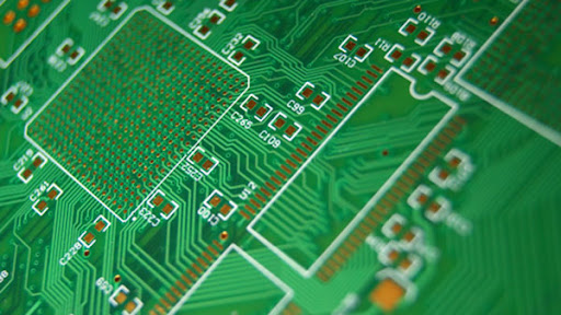
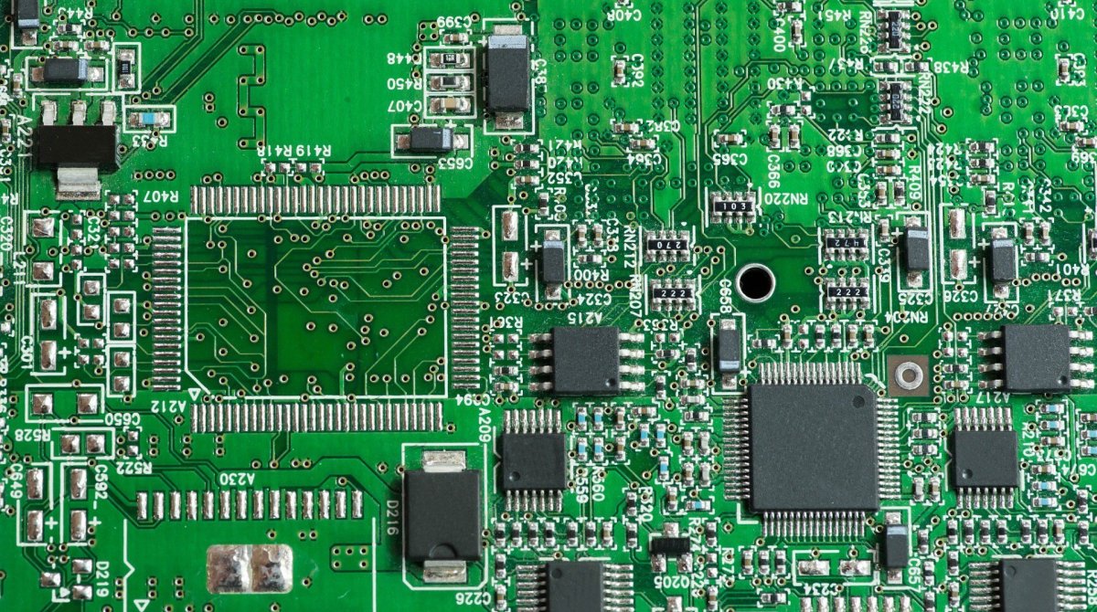
Важность тепловой конструкции пластины PCB Радиочастотные усилители мощности, чипы FPGA, продукты питания и другие электронные устройства потребляют электрическую энергию во время работы, в дополнение к полезной работе, в основном преобразуются в тепло для рассеивания. Тепло, вырабатываемое электронными устройствами, может привести к быстрому повышению внутренней температуры. Если тепло не рассеется вовремя, оборудование продолжит нагреваться, оборудование выйдет из строя из - за перегрева, надежность электронного оборудования снизится. SMT увеличивает плотность установки электронных устройств, уменьшает эффективную площадь охлаждения, а повышение температуры оборудования серьезно влияет на надежность. Поэтому изучение теплового дизайна очень важно. Отопление платы PCB является очень важным звеном, так что давайте обсудим, что такое технология охлаждения платы PCB. Для электронных устройств во время работы вырабатывается определенное тепло, что приводит к быстрому повышению внутренней температуры устройства. Если тепло не рассеется вовремя, оборудование будет продолжать нагреваться, и оборудование выйдет из строя из - за перегрева. Надежность электронных устройств снизится. Поэтому очень важно хорошо охлаждать платы.

2. Фактор повышения температуры печатной пластины анализирует повышение температуры печатной пластины непосредственно из - за наличия энергопотребляющих устройств схемы. Электронные устройства имеют разную степень энергопотребления, а интенсивность нагрева меняется в зависимости от размера энергопотребления. Два явления повышения температуры печатной пластины: (1) локальное или крупномасштабное повышение температуры; (2) Краткосрочное или долгосрочное повышение температуры. При анализе теплового расхода панелей PCB обычно проводится анализ по следующим аспектам. 2.1 Потребление электроэнергии (1) Анализ энергопотребления на единицу площади; (2) Анализ распределения энергопотребления на PCB. 2.2 Структура печатных листов (1) Размеры печатных листов; (2) Материалы для печатной пластины. 2.3 Как установить печатную пластину (1) Метод установки (например, вертикальная установка, горизонтальная установка); (2) 2.4 Тепловое излучение (1) скорость излучения поверхности печатной пластины; (2) Разница температур между печатной пластиной и соседней поверхностью и ее температура 2.5 теплопроводность (1) установка радиатора; (2) 2.6 Теплоконвекция (1) Естественная конвекция; (2) Принудительное охлаждение конвекции. Анализ этих факторов с PCB - панелей является эффективным способом решения проблемы повышения температуры печатных пластин. В продуктах и системах эти факторы часто взаимосвязаны и взаимозависимы. Большинство факторов следует анализировать с учетом реальной ситуации. Конкретные фактические условия позволяют более точно рассчитать или оценить такие параметры, как повышение температуры и энергопотребление. Некоторые методы термического проектирования пластины PCB 1. В настоящее время широко используемыми пластинами PCB являются пластины из медной / эпоксидной ткани или фенолоальдегидной стеклянной ткани с использованием небольшого количества листов из бумаги, покрытых медью. Несмотря на отличные электрические и технологические свойства этих базовых панелей, они имеют плохую теплоотдачу. В качестве метода охлаждения для высокотемпературных элементов практически невозможно ожидать теплопроводности от смолы самого ПХБ, вместо этого излучая тепло с поверхности элемента в окружающий воздух. Однако, поскольку электроника вступает в эпоху миниатюризации компонентов, установки с высокой плотностью и сборки с высоким нагревом, недостаточно полагаться исключительно на поверхность компонентов с очень небольшой поверхностью. В то же время из - за широкого использования поверхностных установочных элементов, таких как QFP и BGA, тепло, генерируемое компонентами, передается в больших количествах на панели PCB. Таким образом, решение для отвода тепла заключается в повышении теплоотдачи пластины PCB, которая находится в непосредственном контакте с нагревательным элементом и передается через пластину PCB. Выйти или отправить. Высокотемперативные компоненты в сочетании с радиаторами и теплопроводными панелями могут добавлять радиаторы или тепловые трубы в нагревательные компоненты, когда небольшое количество деталей в пластине PCB производит большое количество тепла (менее 3). Когда температура не может быть снижена, можно использовать радиатор с вентилятором для повышения теплового излучения. Когда количество нагревательных устройств велико (более 3), можно использовать большие радиаторы (панели), которые основаны на положении нагревательного оборудования на PCB и очень настраиваемых специальных радиаторах, или большие плоские радиаторы. Вырезать различные положения высоты компонентов. Крышка радиатора целиком застегнута на поверхности элемента и контактирует с каждым элементом для охлаждения. Однако из - за низкой степени согласованности компонентов в процессе сборки и сварки эффект охлаждения был плохим. Как правило, для улучшения эффекта охлаждения на поверхность элемента добавляется мягкая термофазная тепловая прокладка. Для устройств, использующих охлаждение свободного конвективного воздуха, интегральные схемы (или другие устройства) расположены вертикально или горизонтально. Использование разумной конструкции проводки для достижения охлаждения из - за плохой теплопроводности смолы в пластине, медная фольга и отверстия являются хорошими тепловыми проводниками, поэтому увеличение остаточной мощности медной фольги и отверстия для теплопроводности является основным средством охлаждения. Чтобы оценить теплоотдачу пластины PCB, необходимо рассчитать эквивалентную теплопроводность композита, состоящего из различных материалов с различной теплопроводностью - изоляционной подложки пластины PCB. Оборудование на одном и том же печатном листе должно быть размещено, насколько это возможно, в соответствии с его теплотой и теплоотдачей. Оборудование с низкой или низкой теплостойкостью (например, небольшие сигнальные транзисторы, небольшие интегральные схемы, электролитические конденсаторы и т.д. В горизонтальном направлении мощные устройства расположены как можно ближе к краю печатной пластины, чтобы сократить путь теплопередачи; В вертикальном направлении мощные устройства размещаются как можно ближе к верхней части печатной пластины, чтобы снизить температуру других устройств во время работы этих устройств. Воздействие 7. Отопление печатных плат в оборудовании в основном зависит от воздушного потока, поэтому при проектировании следует изучить путь воздушного потока и разумно настроить оборудование или печатные платы. Когда воздух течет, он всегда имеет тенденцию течь в местах с низким сопротивлением, поэтому при настройке оборудования на печатных платах избегайте использования

4.1 Выбор материала 4.1 (1) Повышение температуры провода пластины PCB в результате электрического тока плюс указанная температура окружающей среды не должно превышать 125 градусов по Цельсию (обычно типичные значения, которые могут отличаться в зависимости от выбранной пластины). Поскольку компоненты, установленные на печатных платах, также излучают некоторое количество тепла, что влияет на рабочую температуру, эти факторы должны учитываться при выборе материалов и конструкции печатных листов, а температура в горячей точке не должна превышать 125 градусов по Цельсию. По возможности выбирайте более толстое медное покрытие. (2) В особых случаях можно выбрать алюминиевую основу, керамическую основу и другие пластины с низким тепловым сопротивлением. (3) Использование многослойной конструкции пластины облегчает тепловую конструкцию пластины PCB. 4.2 Обеспечить бесперебойное прохождение канала охлаждения (1) в полной мере использовать расположение элементов, медную кожуру, открытые окна и отверстия для охлаждения, создать разумный и эффективный канал с низким тепловым сопротивлением, чтобы обеспечить плавный выход тепла из пластины PCB. (2) Установка отверстия для отвода тепла спроектирована таким образом, что некоторые отверстия для отвода тепла и слепые отверстия могут эффективно увеличивать площадь отвода тепла и уменьшать тепловое сопротивление, увеличивая плотность мощности монтажной платы. Например, на сварном диске устройства LCCC устанавливается перфорация. Сварочный материал заполняется в процессе производства схемы для повышения теплопроводности. Тепло, вырабатываемое в процессе работы цепи, может быстро передаваться через сквозные или слепые отверстия на металлический радиатор или на медную подушку на обратной стороне для охлаждения. В некоторых конкретных случаях платы с радиатором специально предназначены и используются. Теплоотводящие материалы обычно представляют собой медь / молибден и другие материалы, такие как печатные пластины, используемые в некоторых модульных источниках питания. (3) Использование теплопроводного материала для снижения теплового сопротивления в процессе теплопроводности, использование теплопроводного материала на контактной поверхности между энергопотребляющим устройством и подложкой для повышения эффективности теплопроводности. (4) Этот технологический метод может вызвать локальную высокую температуру в определенных областях, установленных по обе стороны оборудования. Чтобы улучшить условия охлаждения, в пасту можно добавить небольшое количество меди, и под устройством после плавки будет определенное количество точек сварки. Высокий Увеличен зазор между оборудованием и печатной пластиной, увеличено конвективное охлаждение. 4.3 Требования к компоновке компонентов (1) Программный термический анализ пластин PCB, проектирование и контроль внутреннего повышения температуры; (2) Можно было бы рассмотреть вопрос о специальном проектировании и установке на печатных платах тепловыделяющих и радиоактивных компонентов; (3) Теплоемкость листов распределена равномерно. Не концентрируйте внимание на высокомощных компонентах. Если это неизбежно, поместите короткие детали вверх по течению потока и убедитесь, что достаточное количество охлаждающего воздуха течет через концентрированную область теплового расхода; (4) сделать путь теплопередачи как можно короче; (5) Максимально возможное поперечное сечение теплопередачи; (6) Компоненты должны быть сконструированы таким образом, чтобы учитывать воздействие теплового излучения на окружающие компоненты. Теплочувствительные компоненты (включая полупроводниковые приборы) должны быть удалены от источника тепла или изолированы; (7) (жидкая среда) удерживает конденсатор от источника тепла; (8) Обратите внимание на направление принудительной и естественной вентиляции; (9) Дополнительные подсистемы и вентиляционные трубы оборудования имеют такое же направление, как и вентиляция; (10) Максимальное расстояние между впускаемыми и выхлопными газами; (11) Обогревательные устройства должны быть размещены, насколько это возможно, над изделием и, если позволяют условия, в каналах воздушного потока; (12) Компоненты с высокой температурой или высоким током не должны размещаться в углах и периферийных краях печатной платы. Они должны быть установлены на радиаторе как можно дольше, вдали от других компонентов и обеспечивать беспрепятственный доступ к радиатору; (13) (периферийные устройства малогабаритных усилителей сигналов) Максимально возможное использование оборудования с малым температурным дрейфом; (14) Использовать, насколько это возможно, металлический ящик или коробку для охлаждения. 4.4 Требования к проводке (1) Выбор пластины (разумное проектирование конструкции печатной пластины); (2) Правила подключения; (3) Планирование ширины канала в соответствии с плотностью тока устройства; Особое внимание уделяется прокладке каналов на стыке; (4) Линии высокого тока должны быть максимально поверхностными; Если требования не выполнены, можно рассмотреть вопрос об использовании шины; (5) Сведение к минимуму теплового сопротивления контактной поверхности. Поэтому площадь теплопроводности должна быть расширена; Контактная поверхность должна быть гладкой и гладкой, при необходимости может быть покрыта теплопроводным силиконовым жиром; (6) Рассмотрим меры по балансировке напряжений в точках теплового напряжения и утяжелите линии; (7) Медная кожура для охлаждения требует использования метода открытия окна под напряжением охлаждения и надлежащего открытия окна с помощью крышки с сопротивлением охлаждения; (8) Если возможно, используйте медную фольгу большой площади на поверхности; (9) В наземных монтажных отверстиях на печатных пластинах используются более крупные прокладки, которые в полной мере используют медную фольгу для установки болтов и поверхностей печатных пластин для охлаждения; (10) Поместите как можно больше металлических перфораций, апертура и поверхность диска должны быть как можно больше, полагаясь на перфорации, чтобы помочь рассеять тепло; (11) Дополнительные средства охлаждения оборудования; (12) Метод добавления радиатора может не использоваться по экономическим соображениям, если можно гарантировать большую площадь медной фольги на поверхности