The names of the circuit boards are: ceramic circuit boards, alumina ceramic circuit boards, aluminum nitride ceramic circuit boards, circuit boards, PCB board, aluminum substrates, high-frequency boards, thick copper boards, impedance boards, PCBs, ultra-thin circuit boards, ultra Thin circuit boards, printed (copper etching technology) circuit boards, etc. The circuit board makes the circuit miniaturized and intuitive, which plays an important role in the mass production of fixed circuits and optimizing the layout of electrical appliances. The circuit board can be called a printed circuit board or a printed circuit board. The English name is (Printed Circuit Board) PCB, (Flexible Printed Circuit board) FPC circuit board[1] (FPC circuit board is also called flexible circuit board. A highly reliable and excellent flexible printed circuit board made of imide or polyester film as the base material. It has the characteristics of high wiring density, light weight, thin thickness and good flexibility!) Soft and hard combinaon plate (reechas, Soft and hard combinaon plate)-The birth and development of FPC and PCB, gave birth to the new product of soft and hard combinaon plate. Therefore, the rigid-flex board is the flexible circuit board and the rigid circuit board. After pressing and other processes, they are combined according to the relevant process requirements to form a circuit board with FPC characteristics and PCB characteristics.
According to the number of layers, the circuit board can be divided into three major categories: single-sided board, double-sided board, and multi-layer circuit board. The first is a single panel. On the most basic PCB, the parts are concentrated on one side, and the wires are concentrated on the other side. Because the wires only appear on one side, this kind of PCB is called a single-sided circuit board. Single-sided panels are usually simple to manufacture and low in cost, but the disadvantage is that they cannot be applied to products that are too complex.
Double-sided boards are an extension of single-sided boards. When single-layer wiring cannot meet the needs of electronic products, double-sided boards should be used. There are copper-clad wires on both sides, and the lines between the two layers can be connected through vias to form the required network connections.
Multi-layer board refers to a printed board with more than three conductive pattern layers and insulating material between them laminated at intervals, and the conductive patterns between them are interconnected as required. Multilayer circuit boards are the product of the development of electronic information technology in the direction of high speed, multi-function, large capacity, small volume, thinner and lighter weight.
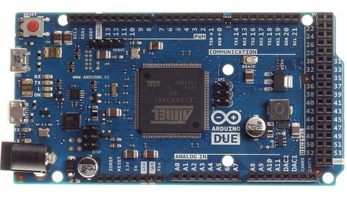
Circuit boards are divided into flexible board (FPC), rigid boards (PCB), and rigid-flex boards (FPCB) according to their characteristics.
Usually, a complete machine is composed of several printed circuit boards, which can be large or small. The circuit contained on each printed board is often drawn on a circuit diagram. Therefore, a complete machine circuit diagram is often composed of several plate circuit diagrams. After you understand each plate circuit diagram, you can understand the complete machine circuit diagram. Each plate circuit diagram includes one or several circuit systems, and the complexity of the large plate circuit diagram It is almost the same as the circuit diagram of an ordinary small and medium-sized screen TV. Although the circuit is relatively complicated, and various plate circuits perform different functions, they have rules to follow and can be read by gathering together in a certain way.
In order to avoid detours when reading circuit diagrams, correct reading methods and steps should be used. Usually adopt the method of outflanking, from outside to inside. By adopting the method of combining internal and external, connecting back and forth, and breaking through step by step, all circuit diagrams can be read more smoothly. The specific method steps of looking at the picture can be summarized in three sentences and three steps: start with the outside, choose the entrance; open the gap, contact the front and back; analyze the difficulties, and put it at the end.

In other words, first look at the most intuitive and easy-to-read components and circuits at the edge of the circuit as the entrance to the picture. A number of circuits or integrated blocks can be found from these peripheral readable parts along the signal line inward (possibly opposite to the signal flow direction).
Open the gap, before and after contact
There are some weak links in any kind of circuit diagram. The complexity and difficulty of each part of the circuit are always different, or the graphics and symbols of some components are different from the general components. These places are the internal weaknesses of the picture, and they are easy to read. They can be used as pictures for viewing. The internal breakthrough. You can choose these places as the breakthrough for reading the picture. After opening the gap, you can quickly connect forward, backward, left and right, and in conjunction with the first step method, you can read many circuits.
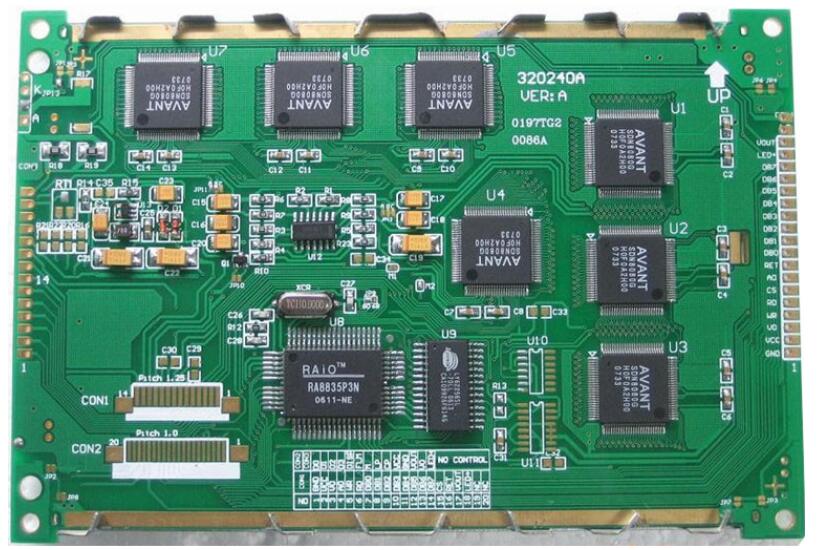
As long as the reader pays attention, there will always be many links that readers are already familiar with in the circuit diagram. Grasp it to quickly open the gap in the picture and develop in depth. The most intuitive and easy-to-read internal link is the integrated circuit, especially those large-scale integrated circuits. They have more than 40 pins, and more than 100 pins. They are very eye-catching in the figure.
They are often placed in the center or obvious location of the circuit diagram. Then, expand outward with these integrated circuits as the center, and you can find
Many circuits. There is a prerequisite for using integrated circuits as internal breakthroughs. You must know the specific types of these integrated circuits, know the main functions of the type of integrated circuits, and be familiar with the names and uses of their main pins. Otherwise, it will bring a lot of inconvenience to the image reading. Sometimes readers are already familiar with most of the integrated circuits, but are not familiar with some of their individual integrated circuits. Based on the composition block diagram and the context, the function of the unknown integrated circuit can also be guessed.
There are also some easy-to-read and easy-to-memorize content in the circuit diagram, which can also be used as a breakthrough in the circuit. For example, the Chinese characters, foreign letters or abbreviations marked in the figure, some important and easy-to-read graphic symbols of components, some adjustable resistors or potentiometers, etc. In order to be able to use these breakthroughs conveniently and smoothly, readers should be familiar with the physical meaning of various foreign letters and abbreviations, have a certain foreign language foundation (usually English), and readers should be familiar with some professional terms and abbreviations frequently used in audio-visual equipment. ; Readers should be familiar with the functions, parameters and indicators of these components. Readers have a wider range of knowledge, which is conducive to reading pictures, and readers should consciously memorize some useful common sense.