Usually radio frequency (RF) and microwave (MW) circuits with operating frequencies above 1 GHz are defined as high frequency circuits. The substrate material it uses is called high-frequency copper clad laminate. For special circuit boards with higher electromagnetic frequencies, generally speaking, high frequency can be defined as a frequency above 1GHz. Its various physical properties, accuracy, and technical parameters require very high requirements, and are often used in automotive anti-collision systems, satellite systems, radio systems and other fields.
The high frequency board/microwave radio frequency board focuses on two parameters: the dielectric constant Dk and the dielectric loss factor Df:
v=K1∗c/(Dk)^0.5
The transmission speed of microwaves in high-frequency circuits is determined by the speed of light (c) and the dielectric constant of the insulating layer. According to the above formula, it can be seen that the lower the Dk, the faster the signal transmission speed.
Dielectric loss=K2*Df*Dk1/2/c

In the signal transmission process, there will be some signal loss, and the higher the frequency, the greater the loss. It includes conductor loss and dielectric loss. The conductor loss is proportional to the square root of Dk, and the dielectric loss is proportional to the square root of Dk. The square root is proportional to the tangent of the dielectric loss Df. The higher the Df, the more obvious the dielectric conductance and dielectric hysteresis, and the more power loss or signal loss.
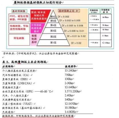
Generally speaking, CCL can be divided into six layers according to the two parameters of Dk and Df. Among them, the substrates used in microwave and millimeter wave frequency bands mainly use low dielectric constant resin (PTFE, hydrocarbon and PPE resin), and the dielectric loss Df<0.005. It can be widely used in high frequency communication fields such as wireless communications above GHz, microwave components, automotive electronics, satellite broadcasting & communications, military radars, etc.
Shenzhen Mingchengxin Circuit Technology Co., Ltd. is mainly engaged in the production services of high-frequency microwave radio frequency induction printed circuit boards and double-sided multilayer circuit boards for quick samples and small and medium batches. The main products are: PCB high-frequency boards, Rogers circuit boards, high-frequency circuit boards, high-frequency microwave boards, microwave radar antenna boards, high-frequency boards, microwave radio frequency boards, microstrip circuit boards, antenna circuit boards, heat dissipation circuit boards, high High-frequency high-speed circuit board, Rogers/Rogers high-frequency board, ARLON high-frequency board, mixed dielectric laminate, special circuit board, F4B antenna board, antenna ceramic board, radar sensor PCB, special circuit board manufacturer, slot antenna, RF antenna, Broadband antennas, frequency sweep antennas, microstrip antennas, ceramic antennas, power splitters, couplers, combiners, power amplifiers, dry amplifiers, base stations, etc.
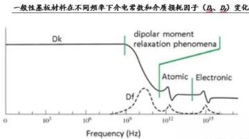
Under the condition of frequency change, general substrate materials show the law of large changes in Dk and Df values (as shown in the figure below). The change trend of Dk is that it becomes smaller as the frequency increases; Df is affected by frequency changes (especially changes in the high-frequency range), and the change of Df value is larger than Dk, and its changing law tends to increase. . Therefore, when evaluating the high-frequency characteristics of a substrate material, it is necessary to pay special attention to the change characteristics of the material Dk at different frequencies; for the requirements for high-speed signal transmission or characteristic impedance control requirements, the focus is on Df and its frequency, Performance under temperature and humidity conditions.

The production process of high frequency board/microwave radio frequency board is similar to that of ordinary copper clad laminate:
1. Glue mixing: The special resin, solvent, and filler are pumped into the glue mixing tank through a pipeline according to a certain proportion and stirred. The materials need to be stirred to prepare a viscous glue with fluidity.
2. Gluing and drying: pump the mixed glue into the glue tank, and at the same time continuously immerse the glass fiber cloth into the glue tank through the gluing machine to make the glue adhere to the glass fiber cloth. The glued glass fiber cloth enters the glue machine oven and is dried at high temperature to become a bonded sheet.
3. Stack the BOOK after cutting the sticky slices: The dried sticky slices are trimmed as required, and the sticky slices (1 or more) and copper foil are stacked and transported to the clean room. Use an automatic book stacking machine to combine the prepared material and the mirror steel plate.
4. Laminating: Send the assembled semi-finished product from the automatic conveyor to the hot press for hot pressing, so that the product can be kept in a high temperature, high pressure and vacuum environment for several hours, so that the bonding sheet and the copper foil are connected together, and finally It becomes the finished copper clad laminate with surface copper foil and intermediate insulating layer.
5. Cutting board: After cooling, trim the extra side strips of the disassembled product, and cut it into corresponding size according to customer requirements.