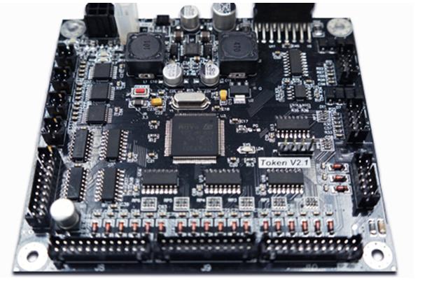
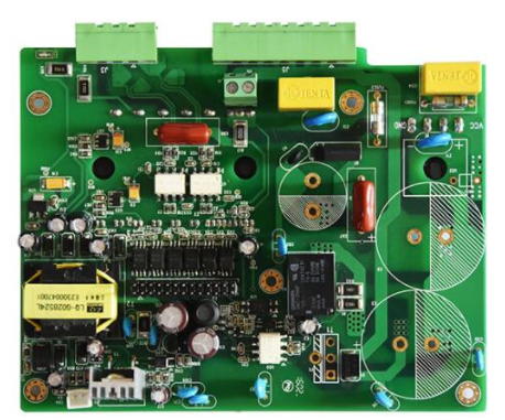
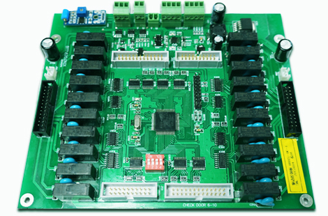
One, look first and then measure
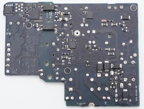
The circuit board to be repaired should first be visually inspected. If necessary, it should be observed with the help of a magnifying glass.
mainly see:

1. Are there any broken wires and short circuits; especially, whether the printed board connecting wires on the circuit board are broken or stuck;
2. Whether the relevant components such as resistors, capacitors, inductors, diodes, transistors, etc. are disconnected;
3. Has anyone repaired it? Which components have been moved? Are there any problems such as false soldering, missing soldering, plugging, and wrong insertion.
Two, first outside and then inside
If the situation permits, it is better to have a good circuit board as the board to be repaired as a reference, and then use the double-bang VI curve scanning function of the tester to compare the good and bad of the two boards. The initial comparison test point can start from the port of the circuit board; then the comparison test from the table to the inside, especially the capacitor, can make up for the shortcoming of the multimeter that it is difficult to detect the leakage of the capacitor online.
three: easy first and harder
In order to improve the test effect, some technical treatments should be done on the repaired board before the online function test of the circuit board to minimize the impact of various interferences on the test process. The specific measures are as follows:
1. Preparation before the test
Short-circuit the crystal oscillator (note that for the four-pin crystal oscillator, make sure that the two pins are the signal output pins. You can short-circuit these two pins. Remember that the other two pins are the power pins. Do not short-circuit!) For large-capacity electrolytic capacitors Solder a pin to make it open, because the charging and discharging of large-capacity capacitors will also bring interference.
2. Use the elimination method to test the device
During the on-line test or comparison test of the device, if the device passed the test (or relatively normal), please directly confirm the test result and record it. If the test fails (or relatively out of tolerance), you can test it again. If it still fails, you can confirm the test result first, and continue the test until the device on the board is tested (or compared). Then, you can deal with those devices that have failed the test (or are out of tolerance).
For devices that fail the functional online test, some test instruments also provide a less formal but more practical processing method: because the power supply of this test instrument to the circuit board can also be applied to the corresponding power and ground of the device through the test clip If the power pin of the device is cut on the pins, the device will be separated from the circuit board power supply system.
At this time, perform online functional test of the device; because other devices on the circuit board will not be powered to work to eliminate the interference effect, the actual test effect at this time will be equivalent to the "quasi-offline test" accuracy rate will be very large improve.