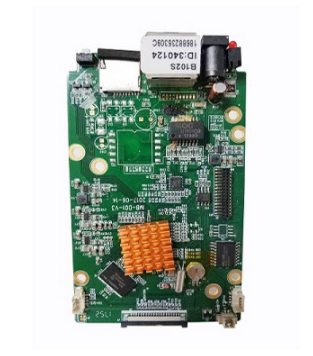
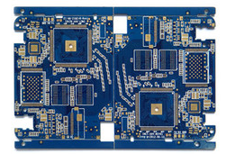
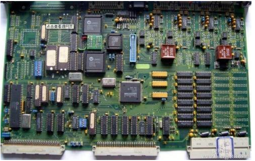
What are the principles of PCB circuit board decoupling capacitor configuration?
PCB factory: In the DC power supply loop, the change of the load will cause the power supply noise. For example, in digital circuits, when the circuit changes from one state to another, a large spike current will be generated on the power line, forming a transient noise voltage. The configuration of decoupling capacitors can suppress noise caused by load changes, which is a common practice in the reliability design of printed circuit boards. So, what are the principles of PCB decoupling capacitor configuration?
PCB circuit board decoupling capacitor configuration
Connect a 10-100uF electrolytic capacitor across the power input terminal. If the location of the printed circuit board allows, the anti-interference effect of using an electrolytic capacitor above 100uF will be better.

2. Configure a 0.01uF ceramic capacitor for each integrated circuit chip. If the printed circuit board space is small and cannot be installed, one 1-10uF tantalum electrolytic capacitor can be configured for every 4-10 chips. The high-frequency impedance of this device is particularly small, and the impedance is less than 1Ω in the range of 500kHz-20MHz. And the leakage current is very small (less than 0.5uA).
3. For devices with weak noise capability and large current changes during turn-off and storage devices such as ROM and RAM, a decoupling capacitor should be directly connected between the power line (Vcc) and ground (GND) of the chip.
4. The leads of decoupling capacitors should not be too long, especially high-frequency bypass capacitors.
The above are some general principles for the configuration of PCB circuit board decoupling capacitors. In the design, it is necessary to carry out corresponding processing according to the specific circuit in order to ensure the reliability of the printed circuit board to the greatest extent. iPCB is a high-tech manufacturing enterprise focusing on the development and production of high-precision PCBs. iPCB is happy to be your business partner. Our business goal is to become the most professional prototyping PCB manufacturer in the world. Mainly focus on microwave high frequency PCB, high frequency mixed pressure, ultra-high multi-layer IC testing, from 1+ to 6+ HDI, Anylayer HDI, IC Substrate, IC test board, rigid flexible PCB, ordinary multi-layer FR4 PCB, etc. Products are widely used in industry 4.0, communications, industrial control, digital, power, computers, automobiles, medical, aerospace, instrumentation, Internet of Things and other fields.