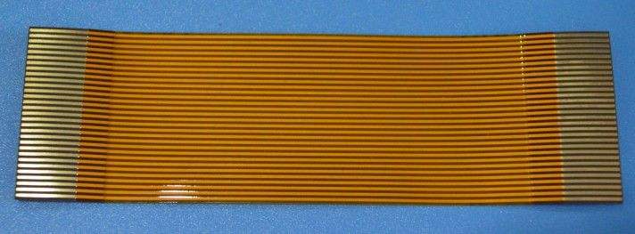
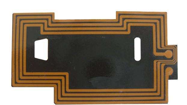
FPC (Flopy print circit) plays a pivotal role in electronic parts with its flexibility and deformability, but its process is different from PCB (print circit board). Now we understand FPC flexible circuit board from the perspective of process flow. Craft.
1. Tooling production
The thickness of FPC flexible circuit boards is generally less than 0.5mm and the number of placement points is limited, so tooling is made in the process to facilitate printing and patching.
1. Material: The tooling material should have a certain mechanical strength, and the density should be relatively low. It is more appropriate to choose aluminum alloy. Some parts must be avoided during double-sided production, so the thickness is generally 2.0mm.
2. Jigsaw: In order to improve the output and the actual utilization rate of the machine, the jigsaw production is generally adopted, and the data of the jigsaw is according to the size of the veneer. It depends on the placement accuracy, generally 6-10PCS is better.
3. Processing: Processing (milling, drilling, leveling) the corresponding parts of the tooling on the milling machine (B side parts avoidance, reinforcement board). When necessary, the corresponding supporting positioning tooling (gusset base) must be made.
2. Steel mesh (Stencil) production and use After positioning the FPC in the tooling, you can send it to the outsourcing factory (steel mesh manufacturer) to customize the steel mesh according to the production requirements.
1. Steel mesh thickness: The thickness of the steel mesh is generally 0.1-0.2mm. For fine pitch IC (0.4pitch) or BGA and CN, 0.12mm is better.
2. Steel mesh opening: the steel mesh opening and production method are the same as the ordinary PCB process, so I won't elaborate here.
3. The use of steel mesh: due to the use of the tooling PCB mesh city, the degree of wear of the steel mesh scraper is relatively serious, so key parameters such as its tension and flatness must be measured regularly.

3, printing (printing)
1. After adopting the joint production, it is necessary to buckle the FPC flexible circuit board. When buckling the board, use the positioning pin as the reference point, and fix the corresponding parts with high-temperature adhesive paper. In addition, the FPC flexible circuit board can be positioned by applying high-temperature double-sided adhesive at the bottom to reduce the workload of sticking high-temperature adhesive paper. Due to environmental factors such as sheet glass, the high-temperature double-sided tape must be replaced regularly. 2. Printing parameter setting: printing with tooling production
4, the patch (mount)
1. Jigsaw production reduces the time of entering and exiting the board to a certain extent, but in order to ensure the stability of the placement, it is necessary to read the fiducial mark for each single FPC before mounting.
2. The program must be expanded according to the puzzle data. optimization.
3. Because FPC products are mainly used for connection (such as flip phones, laptops), some special-shaped parts, such as plugs with a length of 35mm, are often attached. At this time, some special nozzles must be made to ensure that they are in production. Pick and place stability.
4. In addition, because the tooling production is thicker than FPC, the PCB Thickness option in the program must be set according to the tooling thickness when making the program.
5. Reflow:
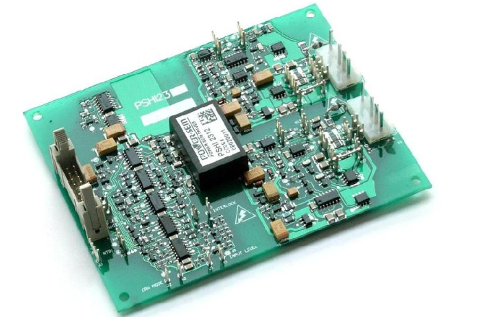
At present, most FPCs in SMT are soldered by hot air reflow with lead solder. We analyze the soldering process of FPC and PCB on this basis. PCB Process Furnace Temperature FPC Process Furnace Temperature Type Items Temperature Rise Rate Constant Temperature Time Peak Reflow Time FPC 1.5 degree Celsius/S 112.4S 216.6 degree Celsius 59.79 S PCB 1.6 degree Celsius/S 98.5S 227.6 degree Celsius 69.3 S Comparison shows: Although FPC adopts tooling production, However, because the substrate material is not resistant to high temperatures, the peak reflow time is relatively shorter than the PCB process.
6. Reflow effect:
The main problems in the FPC flexible circuit board process are as follows:
1. Errors in board assembly (gussets, steel mesh production, and programming may occur) resulting in short circuits. Shift and less tin.
2. The distance between the two PADs is roughly so that the hard parts are falsely welded.
3. Substrates, components, and tooling have different thermal expansion coefficients and cracking caused by folding during the production process.
4. The solder mask on the FPC flexible circuit board is immersed on the PAD and the copper is exposed. The exposed copper FPC is the pivot of the SMT process, and efforts to improve the first pass rate of FPC will still be the goal of major EMS companies.
7, test. Repair
A0I (Automated Optical Inspection) of FPC products. FCT (Functional Testing). ICT (In Circuit Testing) and other testing and rework methods are basically the same as the PCB process.