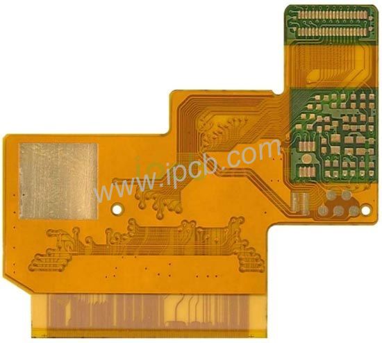
Precision control skills and methods of PCB board milling
The milling technology of the circuit board CNC milling machine includes selecting the direction of the tool, the compensation method, the positioning method, the structure of the frame, and the cutting point, which are all important aspects to ensure the accuracy of the milling process. The following is the accuracy of the PCB board milling process summarized by the editor PCB Control skills and methods.
Cutting direction and compensation method:
When the milling cutter cuts into the plate, one of the faces to be cut is always facing the cutting edge of the milling cutter, and the other side is always facing the cutting edge of the milling cutter. The former has smooth surface to be processed and high dimensional accuracy. The spindle always rotates clockwise. Therefore, whether it is a CNC milling machine with a fixed spindle movement or a fixed spindle movement, when milling the outer contour of the printed board, the tool must be moved counterclockwise.
This is commonly referred to as up milling. Climbing milling is used when milling the frame or slot inside the circuit board. Milling compensation is when the machine tool automatically installs the set value when milling, so that the milling cutter automatically offsets half of the set milling cutter diameter from the center of the milling line, that is, the radius distance, so that the milling shape and program settings be consistent. At the same time, if the machine tool has a compensation function, you must pay attention to the compensation direction and the command of the program. If the compensation command is used incorrectly, the shape of the circuit board will be more or less equivalent to the length and width of the milling cutter diameter.

Positioning method and cutting point:
There are two types of positioning methods; one is internal positioning, and the other is external positioning. Positioning is also very important for craftsmen. Generally, the positioning plan should be determined during the pre-production of the circuit board.
Internal positioning is a universal method. The so-called internal positioning is to select mounting holes, plug holes or other non-metallized holes in the printed board as positioning holes. The relative position of the holes is to be on the diagonal and to choose as large a diameter hole as possible. Metallized holes cannot be used. Because the difference in the thickness of the plating layer in the hole will affect the consistency of the positioning hole you choose, and at the same time, it is easy to cause the plating layer in the hole and the edge of the hole to be damaged when the board is taken. Under the condition of ensuring the positioning of the printed board, the number of pins will be less The better.
Generally, two pins are used for small plates and three pins are used for large plates. The advantages are accurate positioning, small deformation of the plate shape, high accuracy, good shape, and fast milling speed. Disadvantages: There are many types of holes in the board that need to prepare pins of various diameters. If there are no available positioning holes in the board, it is more cumbersome to discuss with the customer to add positioning holes in the board during the preliminary production. At the same time, the different management of milling templates for each type of board is troublesome and expensive.
External positioning is another positioning method, which uses positioning holes on the outside of the board as the positioning holes for the milling plate. Its advantage is that it is easy to manage. If the pre-production specifications are good, there are generally about 15 types of milling templates. Due to the use of external positioning, the board cannot be milled and cut at one time, otherwise the circuit board is very easy to damage, especially the jigsaw, because the milling cutter and the dust collector will bring the board out, causing the circuit board to be damaged and the milling cutter to break.
Using the method of segmented milling to leave the joint points, first mill the plate. When the milling is finished, the program pauses and then fixes the plate with tape, executes the second section of the program, and uses a 3mm to 4mm drill to drill off the joint point. Its advantage is that the template is less expensive and easy to manage. It can mill all circuit boards without mounting holes and positioning holes in the board. It is convenient for small craftsmen to manage, especially the production of CAM and other early production personnel can be simplified, and the substrate can be optimized at the same time. Utilization rate. The disadvantage is that due to the use of drill bits, the circuit board has at least 2-3 raised points that are not beautiful, which may not meet customer requirements, the milling time is long, and the labor intensity of workers is slightly greater.
Frame and cutting point:
The production of the frame belongs to the early production of the circuit board. The frame design not only affects the uniformity of electroplating, but also affects the milling. If the design is not good, the frame is easy to deform or some small pieces are produced during milling. Small scrap, the generated scrap will block the vacuum tube or break the high-speed rotating milling cutter. The frame deformation, especially when positioning the milling plate externally, causes the finished plate to deform. In addition, the cutting point and processing sequence are selected well to enable the frame Maintain the maximum intensity and the fastest speed. If the selection is not good, the frame is easily deformed and the printed board is scrapped.
Milling process parameters:
Use a cemented carbide milling cutter to mill the shape of the printed board. The cutting speed of the milling cutter is generally 180-270m/min. The calculation formula is as follows (for reference only):
S=pdn/1000(m/min)
Where: p: PI (3.1415927)
d: Diameter of milling cutter, mm
n; milling cutter speed, r/min
ipcb is a high-precision, high-quality PCB manufacturer, such as: isola 370hr PCB, high-frequency PCB, high-speed PCB, ic substrate, ic test board, impedance PCB, HDI PCB, Rigid-Flex PCB, buried blind PCB, advanced PCB, microwave PCB, telfon PCB and other ipcb are good at PCB manufacturing.