The mounting hole in PCB board is an important element in electronic design. Every PCB designer will understand the purpose of PCB mounting holes and the basic design. Also, when the mounting hole is connected to the ground, some unnecessary trouble can be saved after installation.
How to use PCB holes to reduce EMI?
As the name suggests, PCB mounting holes help to secure the PCB to the housing. However, this is the physical mechanical use, in addition to the electromagnetic function, PCB mounting holes can also be used to reduce electromagnetic interference (EMI). Emi-sensitive PCBS are usually housed in metal enclosures. To effectively reduce EMI, plated PCB mounting holes need to be connected to the ground. After this grounding shield, any electromagnetic interference will be directed from the metal enclosure to the ground.

A common question asked by the average new designer is which ground do you connect it to? In common electronic devices, there are signals, housing bases and grounding. As a rule of thumb, do not connect mounting holes to signal ground. Signal ground is the reference ground for electronic components in your circuit design, and introducing electromagnetic interference into it is not a good idea.
What you want to connect is the case grounding. This is where all grounding connections of the cabinet converge. Chassis grounding should be connected at a point that is connected through a star. This avoids causing grounding loops and multiple grounding connections. Multiple grounding connections can cause a slight voltage difference and cause current to flow between chassis grounding. The chassis is then grounded to the ground for safety measures.
Why is it important to have proper grounding connections?
If the shell base of the PCB board is a metal shell, then the whole metal shell is the earth. The ground wire of 220V power supply is connected to the earth. All interfaces need to be connected to the earth, and the screws should also be connected to the earth. In this way, incoming interference in EMC testing is discharged directly from the ground to the ground without interfering with the internal system. In addition, EMC protection devices must have each interface, and should be close to the interface.
If it's a plastic case, there's a metal plate embedded in it. If there is no way to achieve, then it is necessary to consider more in the wiring layout, sensitive signal (clock, reset, crystal oscillator, etc.) line needs to protect the ground processing, increase the filter network (chip, crystal oscillator, power supply).
Connecting the plating mounting hole to the chassis floor is a practice, but not a practice to follow. To ensure that your device is protected, your chassis grounding must be connected to the appropriate grounding terminal. For example, if you build an automatic parking payment machine that is not properly grounded, you may have customers complaining of "electric shock" while paying. This may occur when the customer touches the non-insulating metal part of the enclosure.
A mild electric shock may also occur when the computer power chassis is not properly grounded. This can also happen when ground cables connecting power outlets to the floor of a building are disconnected. This may result in floating grounding on the corresponding machine.
The principle of EMI shielding depends on proper grounding connections. Having a floating ground connection not only exposes your customer to a mild electric shock, but can compromise your customer's safety if your device shorts. As shown in the figure below, proper grounding is important for safety and EMI shielding.
Basic techniques for designing PCB mounting holes
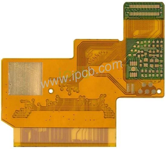
PCB mounting holes are often used in design. There are a few simple basic rules when it comes to mounting holes. First, pay attention to the coordinates of the mounting holes. An error here will directly result in your PCB not being installed correctly in its housing. Also make sure the mounting hole is the right size for the screw you choose.
Do not place mounting holes too far on the edge of the PCB. Too little dielectric material at the edges can cause cracks in the PCB during installation or disassembly. You should also leave enough space between the mounting holes and other parts.
Great circuit design software, such as Altium Designer's sequence software, can place mounting holes and define rules related to safe spacing.