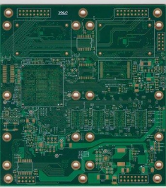
PCB for transient thermal analysis
General electronic component manufacturers provide component specifications, including the maximum temperature for normal operation. The performance of components is usually affected by the ambient temperature or internal temperature of the components. Consumer electronic products often use plastic-encapsulated components with a maximum working temperature of 85 degree Celsius; while military products often use ceramic parts with a maximum working temperature of 125 degree Celsius, and the maximum rated temperature is usually It is 105 degree Celsius. PCB designers can use the "temperature/power" curve provided by the device manufacturer to determine the power dissipation of the component at a certain temperature.
A better compromise is to perform rated and worst-case analysis separately under steady-state conditions.
PCB is affected by various types of heat. Typical thermal boundary conditions that can be applied include:
Natural or forced convection from the front and back surfaces;
The heat radiation from the front and back surfaces;
The conduction from the edge of the PCB to the device shell;
Conduction to other PCBs through rigid or flexible connectors;
The conduction from the PCB to the bracket (bolted or glued);
The conduction of the heat sink between 2 PCB mezzanine layers.
There are many forms of thermal simulation tools. Basic thermal models and analysis tools include general tools for analyzing arbitrary structures, computational fluid dynamics (CFD) tools for system flow/heat transfer analysis, and detailed PCB and component construction. Die PCB application tools.

4.2 Basic process
Under the premise of not affecting and helping to improve the electrical performance of the system, accelerate the PCB thermal design based on the mature experience provided.
On the basis of system and thermal analysis estimation and device-level thermal design, the thermal design results are estimated through board-level thermal simulation, looking for design defects, and providing system-level solutions or changing device-level solutions.
Test the effect of thermal design through thermal performance measurement, and evaluate the applicability and effectiveness of the scheme;
Revise and accumulate thermal simulation models through the continuous practical process of estimation-design-measurement-feedback cycle, accelerate thermal simulation speed and improve thermal simulation accuracy; supplement PCB thermal design experience.
4.3 Board-level thermal simulation
The board-level thermal simulation software can simulate the heat radiation, heat conduction, heat convection, fluid temperature, fluid pressure, fluid velocity and motion vector of the PCB in the three-dimensional structure model. It can also simulate forced heat dissipation, vacuum state or natural heat dissipation, etc. At present, the typical software that can do board-level thermal analysis is Flotherm, Betasoft and so on.
(1) Inspection method of PCB thermal design: thermocouple
The practical application of thermoelectric phenomenon is of course the use of thermocouples to measure temperature. The complex relationship between electron energy and scattering makes the thermoelectric potentials of different metals different from each other. Since the thermocouple is such a device, the difference in thermoelectric potential between its two electrodes is an indication of the temperature difference between the hot and cold ends of the thermocouple. If the thermoelectric potential of all metals and alloys are different, it is impossible to use Thermocouple to measure temperature. This potential difference is called the Scebeek effect. For a pair of conductors A and B of different materials, one junction is maintained at temperature T1, and the two free ends are maintained at a lower temperature To. The contact point and the free end are both located in an area of uniform temperature, and both conductors experience the same temperature gradient. In order to be able to measure the thermoelectric potential difference between the free ends A and B, a pair of conductors C of the same material are respectively connected to the conductors A and B at the temperature to and connected to a detector with a temperature of T1. Obviously, the Seebeck effect is by no means a phenomenon at the connection point, but a phenomenon related to the temperature gradient. In order to correctly understand the performance of thermocouples, this point cannot be overemphasized.
The application range of thermocouple temperature measurement is very wide, and the problems encountered are also various. Therefore, this chapter can only cover some important aspects of thermocouple temperature measurement. Thermocouple is still one of the main methods of temperature measurement in many industries, especially in steelmaking and petrochemical industries. However, with the development of PCB electronics, resistance thermometers have become more and more widely used in industry, and thermocouples are no longer the only and most important industrial thermometers.