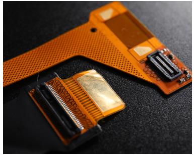
In the last issue of the blog about hard and soft PCB bonding, I talked about the typical process of flexographic board making by ipcb.
Understand the manufacturing process, for the preset hardware and software board or flexible circuit board is often closed. At the same time, it also tells you that you have successfully made the preset value supplied by the wrench.
If you haven't read the first and second parts of this series of blogs, take the opportunity to read them here and here, and then move on. Making documents let's talk about making documents. They are very important.
We make documents to inform the manufacturers that we want them, but they are also the key factors that lead to incorrect understanding or error and costly delay.
Fortunately, we can refer to a few standards to ensure that we can communicate with the manufacturer, especially ipc-2223b.
This comes down to the following golden rules: make sure your manufacturer has the experience to make your default hardware and software board. Make sure they work with you from the time they build the overlapping structure, so that they can be satisfied with their production process by default.
Use ipc-2223 as the default reference and ensure that the manufacturer uses the same or related IPC standards, so you use the same terminology as them.
Let them participate in the preset process as soon as possible. After visiting some local board makers who are experienced in making hard and soft boards, we find that many designers still pass Gerber files to their board makers.
However, the preferred one is ODB + + v7.0 or higher, because it adds special layer types to its office matrix that can be clearly identified by genflex? And similar cam tools.
As shown in Table 1, it contains a subset of values.
Table 1: subset of ODB + + layer types for genflex (v7.0 and higher) (source: ODB + + v7.0 specification) if we use Gerber or an earlier version of ODB + +, we will face a lot of troubles.
In other words, manufacturers need to separate the rigid and flexible circuit local cutting path and die-cutting pattern.
In fact, we need to use the mechanical layer film to reveal the avoidance needs on the hard board, as well as which parts of the flexible circuit area will be exposed; how to use the covering layer to enhance the pad of the components installed on the flexible circuit.
In addition, special attention should be paid to the drilling pairs and through-hole electroplated coating pairs. Since the drilling from the rigid plate to the reverse side of the flexible plate requires re drilling, this will increase the cost and reduce the production.
As a designer, the real question is, how to define the scope, layer and stack of these regions? There is no doubt that the overlapping stack is the most important document for the manufacturer.
In order to make a hard and soft board, we also need to provide different stacks in different fields, and to identify clearly.
A simple way is to make a copy of the outline of the wrench on the mechanical layer, and mark out the areas where there are different overlapping stacks, and put the corresponding overlapping structure table next to it.
An example is shown in Figure 1 below.

Figure 1: stack diagram shows supplementary patterns of hardware and software areas.
In this example, I use different complementary patterns of stack area matching to express which layers are contained in flexible or rigid parts.
You can see that the "insulation 1" here uses the FR-4 because it is a reinforcing plate.