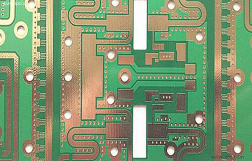
What is High Frequency PCBs?
Radio-frequency (RF) and microwave (MW) circuits can be found in countless wireless products from handheld devices for medical and industrial applications to advanced communications systems for base stations, radar and global positioning. The success of these high-speed products begins at the product design stage when the PCB laminate materials are selected. Rayming works with the product design team to insure that the project’s cost/performance targets can be met by providing information on material options, relative costs and DfM considerations.
The features of high frequency PCB as following
1. DK should be small and stable enough, usually the smaller the better, high DK may lead to signal transmission delay.
2. DF should be small, which mainly affect quality of signal transmission, the smaller DF could make smaller signal wastage accordingly.
3. The thermal expansivity should be the same with copper foil as much as possible, because the difference will lead to copper foil separated in the changes of cold and heat.
4. Water absorptivity must be low, high water absorptivity will affect DK and DF when in the wet environment.
5. Heat resisting property, chemistry resisting, impact endurance, peel off resisting must be good.
Materials:
Rogers, Taconic, Isola, Arlon, SY and etc.
Multi-layer hybrid high-frequency PCB boards need to use materials with very different key characteristics than traditional multi-layer high-frequency PCB boards. The hybrid board can be a mix of FR4 and high-frequency boards, or a mix of high-frequency boards with different DKs. With technological innovation, hybrid structures are becoming more and more popular. This not only brings benefits, but the challenges we face also require us to better understand. There are three main reasons for using mixed plates: cost, improved reliability and enhanced electrical performance. High-frequency line materials are much more expensive than FR4. Sometimes, the mixed voltage of FR4 and high frequency lines can solve the cost problem. In many cases, some circuits of mixed-voltage PCB boards have high requirements for electrical performance, while others have low requirements. In this case, FR4 will be used for parts that do not require high electrical performance, and more expensive high-frequency materials will be used for parts that require high electrical performance. Another reason for using mixed-press multilayer boards is that when the CTE value of the PCB board material used is relatively high, reliability can be improved. Some high-frequency PTFE materials have high CTE characteristics, and this will cause reliability problems. When a low-CTE FR4 material and a high-CTE material are combined to make a multilayer board, the composite CTE is acceptable. The purpose of mixing some materials with different DK is to improve electrical performance. In some combiner and filter applications, the use of mixed voltage of materials with different DK values will help improve electrical performance. The mixing of FR4 and high-frequency materials is becoming more and more common, because FR4 and most high-frequency line materials rarely have compatibility issues. However, there are several circuit board manufacturing issues that are still worthy of attention. The use of high-frequency plates in the mixed pressure structure will cause a great difference in temperature due to the special process. PTFE-based high-frequency materials will bring a lot of problems in the circuit manufacturing process, because special drilling and via plating PTH preparation requirements are required. The plates based on hydrocarbon resins are easy to process, using the same circuit production process as standard FR4, and the technology is just fine. The mixing of FR4 and high-frequency plates based on hydrocarbon resin materials basically has no processing and manufacturing problems. The main problem is drilling and pressing. Want to build a correct bit feed? And drilling speed, design experience is required. The pressing of FR4P sheets is a problem because it requires a ramprate (temperature rise rate?) that is very different from that of hydrocarbon high-frequency materials. In order to have more reliable mixing, there are several options worth considering. First, replace the FR4 P sheet with a high-frequency material P sheet, and use the correct lamination cycle. High-frequency material P sheets are usually not as expensive as copper clad laminates, and the adhesive layer of the same material is more conducive to a simpler lamination cycle. When FR4P sheets cannot be replaced, they must be laminated in order : First press the P sheet of FR4, and then press the P sheet of high-frequency material.
The mixed pressure of FR4 and PTFE materials is more challenging, but there are exceptions. There are different types of PTFE copper clad laminates, some of which are easier to process than others. Even if the ceramic filler PTFE copper clad laminate has fewer processing problems than PTFE, it also needs to consider drilling, PTH via plating preparation and dimensional stability. The biggest problem with PTH drilling is that PTFE material is relatively soft, while FR4 is relatively hard. When drilling PTH and drilling tools, there will be some soft material in the hole extending to cover the hole wall of PTH. This can cause serious reliability problems. Generally, the drill bit and drilling speed must be determined by experienced engineers, and the service life of the drill bit is also worth studying. In many cases, flapdefect does not appear in the early use of the drill bit, so a better understanding of the life of the drill bit is very important to reduce such concerns. ThePTHpreparationmustaddressbothtypesofmaterialsfortheplatedthrough-holeprocess. The plasma cycle may require 2 different cycles or one cycle, but multiple stages. In the first plasma cycle, FR4 material should be processed first, and then PTFE material should be processed in the second cycle. Generally, in the plasma treatment process, FR4 uses CF4-N2-O2 gas, and PTFE uses He or N2H gas. For PTFE material, to improve the wettability of the via hole wall, it is better to use helium (He) helium. If you want to use wet processing when preparing PTH, perform the permanganate process on FR4 first, and then do sodiumnaphthalene treatment on the PTFE material. For the mixed pressure of FR4 and PTFE materials, dimensional stability or scaling will inevitably be a problem. By minimizing the mechanical pressure acting on the PTFE material, the occurrence of problems can be reduced. Scrubbingthepanelinducesrandommechanicalstressesandisnotrecommended. For the next process of preparing copper foil, a chemical cleaning process is a better way. The thicker the PTFE copper clad laminate, the less the problem of dimensional stability. Similarly, the PTFE substrate reinforced with glass fiber will be more stable in terms of size. In general, there is basically no compatibility problem in the mixed-pressure PCB manufacturing of FR4 and high-frequency circuit materials. But several concerns about circuit board manufacturing are still worth noting. In order to have better results, it is recommended that the board factory communicate, exchange, and discuss with the high-frequency PCB manufacturer when it is necessary to mix and press multilayer boards.