How to replace chip components during SMT processing
iPCB is happy to be your business partner. Our business goal is to become the world's most professional prototype PCB manufacturer. With more than ten years of experience in this field, we are committed to meeting the needs of customers from different industries in terms of quality, delivery, cost-effectiveness and any other demanding requirements. As one of the most experienced PCB manufacturers and SMT assemblers in China, we are proud to be your best business partner and good friend in all aspects of your PCB needs. We strive to make your research and development work easy and worry-free.
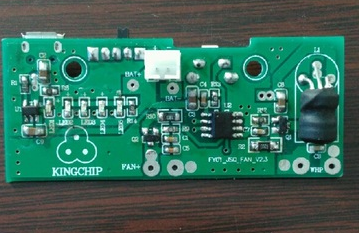
During SMT processing, chip components are one of the materials that have more contact. In SMT processing, chip components need to be replaced from time to time. It seems very simple to replace chip components, but there are still many tricks in it. If you do not pay attention, it is still very troublesome to operate. In order to ensure product quality, we need to replace chip components in strict accordance with relevant requirements.
Before the operation of replacing chip components during SMT processing, we need to prepare an electric soldering iron that is connected to the ground and the temperature can be controlled. The width of the soldering iron tip must match the size of the metal end face of the chip component, and the soldering iron needs to be heated to 320 degrees Celsius. In addition to the electric soldering iron, you also need to prepare basic tools such as tweezers, tin strips, fine low-temperature rosin, and welding wire.

When replacing chip components, you can directly put the heated soldering iron tip on the upper surface of the damaged component, and then wait until the solder on both sides of the chip component and the adhesive under the component are melted by high temperature, you can use tweezers directly The damaged Mrs. component has been removed. After removing the damaged component, you need to use a de-tin strip to suck up the remaining tin on the circuit board, and then wipe the adhesive and other stains on the original pad with alcohol.
WhenPCBA is processed, usually only a proper amount of solder is applied to one pad on the circuit board; then use tweezers to place the component on the pad. In order to quickly heat the tin on the pad, the molten tin contact chip component needs to be placed on the metal end, But there is another point that needs special attention, do not let the soldering iron tip directly touch the component.
Generally, as long as one end of the newly replaced chip component is fixed, the other end can be soldered. It is necessary to heat the pad on the circuit board and add an appropriate amount of solder to form a bright arc surface between the pad and the component end surface. It should be noted that the amount of solder can not be put too much, otherwise the molten solder will flow under the component and cause the pad to short-circuit. Just like the other end of soldering, the remaining end can only allow the molten tin to dip into the metal end of the component. Let the tip of the soldering iron touch the component to complete the entire replacement process.