Using low-cost PCB (printed circuit board), it is easy to design a circuit board with almost any CAD software (even free software) in a few hours. It only takes two days to complete the prototype board on your desk. Many software packages have good design rules. Most PCB manufacturers can produce linewidth and line spacing as low as 0.006 inch.
This accuracy has no problem with low-frequency circuits, but RF circuits generally need 50 Ω wiring to operate normally. The volume of parts is getting smaller and smaller, but the laws of physics will not change. Therefore, a microstrip line on a 0.062 inch thick prototype board today is 0.11 inch wide, compared with 0.11 inch 30 years ago. However, many SMT (surface assembly technology) components are much smaller than their previous generation components. Therefore, the low-cost double-sided board used for RF prototype does not seem to be suitable for today's small SMT components.
Using a cpwg (grounded coplanar waveguide) structure, 50 Ω RF wiring can be fabricated on PCB. Cpwg structure can produce the required routing, and its width is less than that of microstrip structure.

A grounded copper foil on the top board is close to a microstrip line, which increases the capacitance of the microstrip structure. In order to compensate and keep the whole structure at 50 Ω, the central wiring width must be reduced to a certain point to make it have higher inductance.
How to design cpwg structure with low cost and fast PCB process? Many cpwg calculators can be found on the Internet, but when the stratum spacing is less than 30% of the routing width? At 50%, these calculators will fail because the height of copper foil routing on the circuit board becomes a significant factor. It adds more capacitance than the calculator assumes. Therefore, the routing designed by these calculators has too high capacitance, reducing its impedance to less than 50 Ω. These formulas can be traced back to IC design many years ago.
The formulas in many calculators can no longer be used, because today's PCB is essentially different from IC. The best way to correctly design a cpwg with a narrow spacing centerline ratio on a PCB is to use a full three-dimensional electromagnetic simulator. This example provides values for some common structures.
Keeping the minimum routing spacing at 6 mil, I simulated, fabricated and tested a cpwg structure. For the common 0.062 inch thick FR-4 PCB material, a wiring with a width of 0.032 inch and a spacing of 0.006 inch is closest to 50 Ω. At 6 GHz, the return loss of the routing line is better than 40 dB.
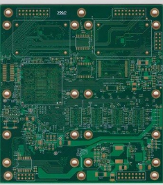
This scheme is better than the method of 0.11 inch wide wiring, and is compatible with SMT components. SMT components of size 0603 and common SMA (surface mount assembly) board edge connectors can perfectly match this wire. Figure 1 compares a variety of common RF components with a prepared PCB. For parts with pad size greater than 0.032 inch routing width, it can be compensated by increasing the gap from the top plate ground. For example, increasing the top clearance from an 0805 SMT pad to about 0.008 inch and a 1206 SMT element pad to 0.012 inch can prevent excessive pad capacitance.
In order to comply with the general design rules, I pulled the copper foil back 0.01 inch from the edge of the laid circuit board on the test PCB. However, this pull back and board side mounted connectors add a small amount of inductance to the conversion. The thick pin in the middle of the board side connector at the end of the wiring adds additional capacitance to provide built-in capacitance compensation. By shortening the pin to about half of its original length, approximately equivalent capacitance can be obtained to balance the conversion inductance.
Cpwg structure requires a solid ground plane under the routing; Leaving an opening on the ground floor below the top layer wiring adds a large inductance to the structure and reduces the high-frequency performance. In addition, some vias need to be used to "stitch" the top ground and the bottom ground. The placement of such stitched vias shall not exceed one eighth of the highest frequency wavelength used by the circuit. Note that 0.1 inch spacing works well at frequencies above 10 GHz.
The spacing from the stitched vias to the center line follows the same spacing rules. Enough vias for normal operation can be easily arranged on the routing line.
If there are not enough vias, a small but fast 0.5dB to 1dB drop will be seen in the transmission characteristics of S21, rather than a linear loss slope with frequency. This effect can be seen immediately with a VNA (vector network analyzer). The measurement of the test board shows that the loss is about 0.25 dB / in at 3 GHz and 1 dB / in at 10 GHz, including two board edge connectors.
If you want to connect SMT devices or IC with pads narrower than 0.032 inches, narrow the center conductor as needed and close to the device as much as possible. If the actual discontinuity is small, its effect can be ignored when the frequency is not very high.