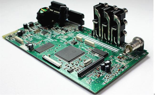
What are the steps and rules for PCB circuit boards
1. Layout according to circuit modules, and related circuits that achieve the same function are called a module. The components in the circuit module should adopt the principle of nearby concentration, and the digital circuit and the analog circuit should be separated;
2. Avoid placing via holes under the horizontally mounted resistors, inductors (plug-ins), electrolytic capacitors and other components to avoid short-circuiting the vias and the component housing after wave soldering;
3. No components or devices shall be mounted within 1.27mm of non-mounting holes such as positioning holes, standard holes, and 3.5mm (for M2.5) and 4mm (for M3) of 3.5mm (for M2.5) and 4mm (for M3) shall not be mounted on components;
4. The distance between the outside of the component and the edge of the board is 5mm;
5. Metal shell components and metal parts (shielding boxes, etc.) can't touch other components, can't be close to printed lines, pads, and their spacing should be greater than 2mm. The size of positioning holes, fastener installation holes, oval holes and other square holes in the board from the outside of the board edge is greater than 3mm;
6. The distance between the outside of the mounting component pad and the outside of the adjacent interposing component is greater than 2mm;
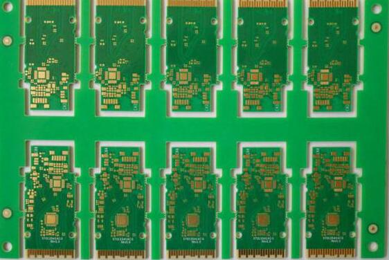
PCB circuit board manufacturers

7. The power socket should be arranged around the printed circuit board as much as possible, and the power socket and the bus bar terminal connected to it should be arranged on the same side. Particular care should be taken not to arrange power sockets and other welding connectors between the connectors to facilitate the welding of these sockets and connectors, as well as the design and tie-up of power cables. The arrangement spacing of power sockets and welding connectors should be considered to facilitate the plugging and unplugging of power plugs;
8. Heating elements should not be in close proximity to wires and heat-sensitive elements; high-heating elements should be evenly distributed;
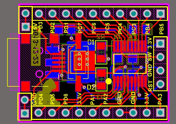
9. Arrangement of other components: All IC components are aligned on one side, and the polarity of polar components is clearly marked. The polarity of the same printed board cannot be marked more than two directions. When two directions appear, the two directions are perpendicular to each other. ;
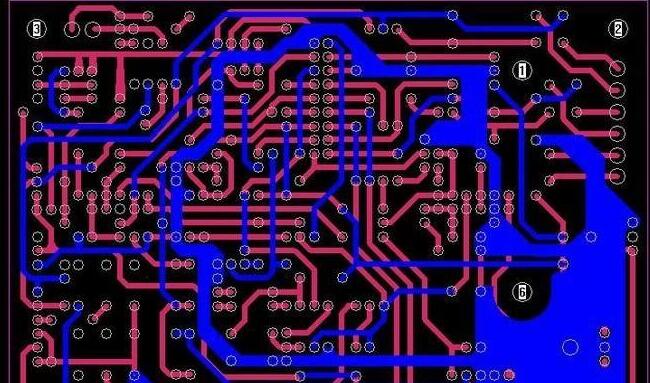
10. The wiring on the board should be dense and dense. When the difference in density is too large, it should be filled with mesh copper foil, and the grid should be greater than 8mil (or 0.2mm);
11. The patch is aligned on one side, the character direction is the same, and the packaging direction is the same;
12. The polarized devices should be consistent as far as possible on the direction of the polarity marking on the same board.
13. There should be no through holes on the SMD pads, so as to avoid the loss of solder paste and cause false soldering of the components. Important signal lines are not allowed to pass between the socket pins;
14. The circuit industry has extremely strict requirements on the workshop environment and the standard operation of employees, especially the chemical reaction environment is required in the production of What are the steps and rules for PCB circuit boards, so the infiltration of impurities is not allowed.