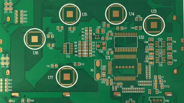
Change of lead-free wave soldering unit for circuit board
1. Brand new Xichi
In order to avoid exceeding the upper limit of 0.1% bywt of lead in solder joints stipulated by the EU Act, or even stricter thresholds for customers (for example, reducing the amount of lead to 0.05% bywt and other internal regulations), it is recommended that the solder pool of the wave soldering wire should be changed to use Brand-new production line tank to completely avoid lead! If using SAC305 solder, it is best to use titanium alloy tank and various accessories to reduce the attack and meltdown faced by stainless steel tank (mp508 will be formed in long-term high temperature) degree Celsius FeSn, IMC, but if the solder is tin-copper-nickel (weight ratio of Sn99.3%, Cu0.7%, Ni0.02-0.05%), stainless steel can still be used because of the greatly reduced aggressiveness.
In order to convert the lead-free production equipment to save its cost, in addition to completely removing the original tin-lead alloy, it is also necessary to add the original molten pure tin in the pool, and continue to circulate for more than 1 hour during the simulation of normal operation, in order to try to Dissolve lead in various dead ends. The operating temperature of this kind of pure tin added to the cleaning tank must be at least 30°C higher than its melting point to be able to clean the tank smoothly, and then the pure tin can be discharged after completion. Such high-temperature work is not only dangerous, but also extremely hard.

2. Central titanium wire
Lead-free wave soldering has a high temperature and a long time. When the parts on the circuit board are too large and too heavy, if only the support of the fingers (FingerS) on both sides is supported, it will inevitably not cause the large board. Soften and warp downward in the central area. This kind of sag deformation often causes the tin wave to rush to the top surface of the board (Component Side), causing the tin wave in the central area to be higher than the two sides of the board, and even the tin melt will flow back from the board surface. Enter the preheating zone. For the sake of improvement, the central titanium wire specially used as a support to prevent sinking must be erected from the flux tank section before preheating and extending to the exit of the final smelting section, so that the board can be continuous during travel. Boosted by support.
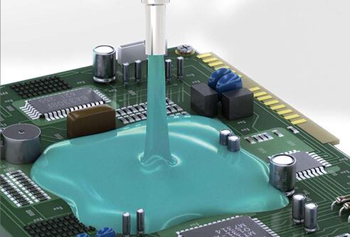
3. Flux coating unit
Usually, flux coating machines for lead wave soldering (Fluxer) have always used foam (FOam) type. However, starting from 2007, the EU may add a VOCFree (VOlatile0rganiCCO1fIpound) in addition to the six prohibited substances in RoHS, which means that "volatile organic compounds" will also be banned. To put it more clearly, it is the thinner in the flux formulation. The current various organic solvents can no longer be used. As a result, the water-soluble flux will become the only legal formula product. This kind of water-based flux with high surface tension is best operated with a "spray type" flux coating unit (Spray Fluxer Unit). The advantages of the spray type are:
1. The spraying unit is a closed system, and the specific gravity of FluX is relatively stable, so there is no need to add a specific gravity controller. It is simpler than the foam type which is easy to volatilize (IPA (isopropyl alcohol)), and there is no need to install a specific gravity management instrument to control its replenishment and addition.
2. The spray-type atomized small water point is easy to enter the through hole, which improves the soldering effect.
3. The spray type can also use two sets of the same or different formula units before and after to improve the flux reaction between the board surface and the hole, which is especially effective for those who frequently change the production board. In order to check the uniformity of the overall spray distribution, a glass plate or thick cardboard can be used for trial walking and observation.
Fourth, the change of preheating section
As the European Union may legislate to ban "volatile organic compounds" in 2007, it is immediately affected that the organic flux in the flux (for example: isopropanol SOprOpy1Alcoho1) will not be able to be renewed. Immediately, only water-based flux will be fully used. Since the boiling point of water is much higher than that of organic solvents, the total heat in the preheating section must be increased to completely drive off the water, and avoid splashing tin during wave soldering, which in turn will cause SOlder Balls on the green paint surface. future trouble.
Five, the difference of wave soldering section wave device
The lead 63/37 eutectic (EuteCtiC) solder has a lower surface tension (ie cohesion) (380dyne/260 degree Celsius), and the Wetting Time is also shorter (0.5-1.0 seconds), so the front part of the tin pool Both the Turbulent Waveor Chip Wave and the Main Wave in the back section will experience a total of about 3-4 seconds in 6 3/3 7 welding (depending on the size of the board). However, after the lead-free era, taking SAC305 as an example, its surface force has increased to 460dyne/260°C, so that when IMC is not easy to generate, the tin dip time has also slowed down and had to be extra 1-2 seconds.
For some products that are sensitive to two-stage high heat, you can also use a single-wave welding machine that combines turbulence (eddy current) and advection wave. Not only can the board surface be safely welded, but also enough tin can be poured into the connecting hole., The management and maintenance of this kind of single loudspeaker is much simpler than the production line of double sets of loudspeakers.
Six, nitrogen environment
If all the wave soldering connections can be put into a nitrogen environment (purchasing nitrogen or a nitrogen generator, after the flux completes the removal of the oxides on the part feet and the PCB pad surface, the subsequent high temperature process will remove the There will be no more rust, so that the solderability and solder joint strength will be better. And the surface of the tin pool will also be reduced due to the oxygen-free state to reduce scum, and reduce the unnecessary loss of high-priced lead-free solder. This will not only save money. The double cost of materials and disposal, and it can also reduce the shortcomings of BridgeS, Icicles, and Spikes caused by the viscous drag of the tin pool. The advantages are briefly described as follows:
.The scum is reduced, the amount of solder is reduced, and the burden of waste disposal can also be reduced.
.Flux activity can be reduced and maintenance can be simplified.
.The solderability is improved, the operating range is enlarged, and the quality and reliability are improved.
In fact, the nitrogen and oxygen environment does not need to reach the point of pure nitrogen. The purchased nitrogen can be continuously blown into the sealed wave solder connection to drive away the air and oxygen. The main point is to drive the oxygen in the dual wave zone. In order to save costs, the residual oxygen rate can be as low as 1500 p p m to show a good welding effect. When the product is not too particular, the residual oxygen rate can be relaxed to 2000 ppm, and the average dosage is about 8-12m2/hr. After the use of nitrogen, due to the reduction of various adverse oxidation effects, the welding temperature can still be reduced by 5-10 degree Celsius while still maintaining the original higher temperature welding effect in the air. With the help of N2, the activity of the flux does not have to be too strong, and the decrease in activity is equivalent to subsequent ion pollution and electrochemical migration" (Electro-Chemical Migration)
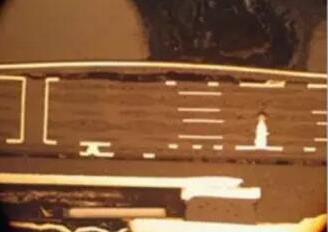
Seven, the second degree of heating of SMT solder joints
The current assembly board not only has a large number of SMT soldering components, but also has a small number of wave soldering that requires pin sockets. Therefore, after all the EEl component side (ComponentSide) has undergone SMT welding (Reflow), another process is required. Wave soldering or selective soldering on one side (Selective Soldering). As a result, the solder joints that have been previously soldered with solder paste will inevitably be subjected to another unfavorable remelting, resulting in loss of their strength. For example, for some QFP's numerous extension legs, the strength of 12N/mm2 can be reached after solder paste soldering. However, after the remelting of the second wave soldering, the average weakened to less than 8N, the main reason is of course the length and thickness of the IMC in the solder joint or the accumulated stress of the bending of the plate.