In the process of PCB copy board design, circuit schematics are often drawn based on the actual object. Therefore, mastering the method of PCB copy board physical drawing and inverting the circuit schematic diagram will be the first procedure for PCB copy board design.
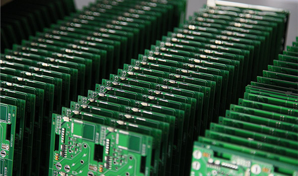
Circuit board factory
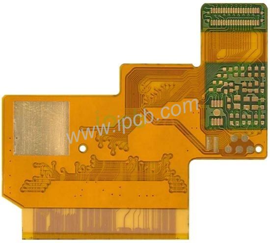
The circuit board factory restores the circuit schematic diagram according to the PCB circuit board
1. The experience given by the circuit board factory is to choose components that are large in size, have many pins and play a major role in the circuit, such as integrated circuits, transformers, transistors, etc. The pin starts to draw, which can reduce errors. Error prevention is also very important in the manufacturing industry.

2. If the printed board is marked with component serial numbers (such as VD870, R330, C466, etc.), because these serial numbers have specific rules, the components with the same first Arabic number after the English letter belong to the same functional unit, so they should be used skillfully when drawing . Correctly distinguishing the components of the same functional unit is the basis of drawing layout. There are many methods in the circuit board manufacturing method of the circuit board factory that can be applied to restore the circuit schematic diagram.
3. If the serial number of the component is not marked on the printed board, it is best to number the component yourself in order to facilitate the analysis and calibration of the circuit. When designing printed circuit board layout components, circuit board manufacturers generally arrange the components of the same functional unit in a relatively concentrated manner in order to make the copper foil traces the shortest. After finding the device that plays a core role in a certain unit, you can find other components of the same functional unit as long as you follow along.
4. According to the experience of the circuit board factory, correctly distinguish the ground wire, power wire and signal wire of the printed board. Take the power supply circuit as an example. The negative end of the rectifier connected to the secondary of the power transformer is the positive pole of the power supply, and a large-capacity filter capacitor is generally connected to the ground, and the capacitor shell has a polarity mark. The power line and ground line can also be found from the pins of the three-terminal regulator. In order to prevent self-excitation and anti-interference, the circuit board factory generally sets the copper foil of the ground wire to the widest (high-frequency circuits often have large-area grounding copper foil), and the copper foil of the power wire is second, and the signal The wire copper foil is the narrowest. In addition, in electronic products with both analog and digital circuits, the printed boards often separate their respective ground wires to form an independent grounding network, which can also be used as a basis for identification and judgment.
5. In order to avoid too many component pin connections to cross the wiring of the circuit diagram, resulting in a messy drawing, a large number of terminal markings and grounding symbols can be used for power and ground wires. If there are more components, you can also draw each unit circuit separately and then combine them together.
6. When drawing a sketch, it is recommended to use transparent tracing paper and use a multi-color pen to classify the ground wires, power wires, signal wires, components, etc. by color. When modifying, gradually darken the color to make the drawing visually and eye-catching so that the circuit can be analyzed.
7. Familiar with the basic composition and classic drawing methods of some unit circuits, such as rectifier bridges, voltage regulator circuits and operational amplifiers, digital integrated circuits, etc. First draw these unit circuits directly to form the framework of the circuit diagram, which can improve drawing efficiency.
8. When drawing circuit diagrams, you should find the circuit diagrams of similar products for reference as much as possible, which will double the result with half the effort. Our circuit board factories and circuit board manufacturers in various places rely on this method to restore the circuit schematic diagrams.