PCB manufacturer: SMT repair detailed steps and operation essentials
1. Purpose
Make SMT maintenance staff familiar with and master all kinds of bad correct maintenance and correct use of various equipment, and work according to operating standards to improve the quality of maintenance products
2. area
Suitable for SMT repair
3. Responsibilities
3.1. Maintenance personnel: responsible for the daily maintenance of defective products and the correct use, cleaning and maintenance of equipment;
3.2. Technician and stretcher: responsible for the supervision and technical guidance of maintenance quality.
4. Preparation:
4.1. Prepare the tools used and confirm whether the heat gun is in working condition
4.2. Understand the models produced by the famous line and the board numbers used
5. Tools:
Tweezers, constant temperature soldering iron, anti-static brush, hot air gun, waste box, anti-static gloves, corded static ring, etc.
6. Material description:
6.1 Tin wire
6.1.1 Tin wire specification: strong ¢0.8MM
6.1.2 Shelf life of tin wire: 1 year, exposure time: 30 days
6.2 Model of patch adhesive: Fuji NE3000S 6.2.1 Maximum use time at ambient temperature after opening the can: 7 days
6.2.2 The storage time of unopened cans in cold storage: 6 months
6.3 Environment-friendly plate washer water
6.3.1 Shelf life: None
6.3.2 Exposure time: none
6.4 Wipe paper
6.4.1 SMT wipe paper
6.5 Rosin, flux
6.5.1 Shelf life of rosin: 1 year
6.5.2 Rosin exposure time: 7 days

7. Homework:
7.1 For the soldering iron temperature test of the repair station, at least once per shift, IPQC fills in the "Soldering Iron Inspection Record Form"
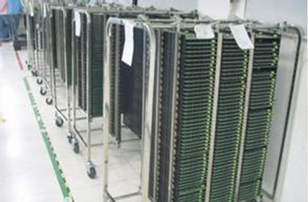
7.2 Take out the PCB board to be repaired from the defective card rack, put it on the repair table and check the defective phenomenon and the defective point
7.3 Repair the positions where the components need to be replaced such as missing parts, body damage, etc.: SOP components
7.4 Component removal
7.4.1 Observe whether there are pollution, oxidation, impurities and foreign matter on the surface of the circuit board. If there is any, clean it with environmentally friendly board washing water and dry it.
7.4.2 Set the temperature of the hot air gun console to 450 degree Celsius
7.4.3 Use a syringe to apply rib flux to the end of the component
7.4.4 When the displayed temperature value reaches the set value, move the hot air gun nozzle to 5±2MM above the removed component to start heating
7.4.5 When the heating time reaches the melting point of the solder, use tweezers to remove the component and reshape it
7.5 Component welding
7.5.1 According to the latest product BOM of the repaired component, prepare the correct component used at this point
7.5.2 Choose a constant temperature soldering iron with a knife-shaped soldering iron tip, and set the temperature of the console: Leaded 340±20 degree Celsius Lead-free 380±20 degree Celsius
7.5.3 Use a syringe to apply ribbed flux on each pad at this point
7.5.4 Clamp the component that has been selected OK with tweezers and place it on the pad (when clamping the component, the tweezers should be clamped on the side of the component body to avoid the component feet)
7.5.5 Take the tin wire, add tin to the tip of the soldering iron, and solder the component pins (when soldering the first pin, the tweezers cannot be removed), clean and self-check SOP components after soldering (there is a dual-row component pin parallel to the External application), QFP components (there are four rows of component pins and external application)
7.6 Component removal
7.6.1 Observe whether there is pollution, oxidation, impurities and foreign matter on the surface of the PCB. If there is, clean it with a cleaning agent and dry it. 7.6.2 Set the temperature of the heat gun console at 450 degree Celsius
7.6.3 Apply rib flux to the end of the component with a syringe
7.6.4 When the displayed temperature value reaches the set value, move the hot air gun nozzle to 5±2MM above the removed component to start heating
7.6.5 When the heating time reaches the melting point of the solder, use tweezers to remove the component for shaping treatment
7.6.6 Check the condition of the removed components. If there are missing feet, broken feet, or poor raw materials, return them to the material staff for processing, and repair the components according to the IC repair instructions.
7.7 Component welding
7.7.1 According to the latest product BOM of the component to be repaired, prepare the correct components used at this point (the components that are OK for trimming should be used first)
7.7.2 Choose a constant temperature soldering iron with a knife-shaped soldering iron tip, and set the temperature of the console: 340±20 degree Celsius for lead and 380±20 degree Celsius for lead-free
7.7.3 Use a syringe to apply flux on each pad at this point
7.7.4 Take the solder suction wire, cover the solder suction wire to the pad at the repair point, use a thermostatic soldering iron at a 45 degree angle to clean the residual solder on the PCB or directly remove it with a soldering iron.
7.7.5 Clamp the component that has been selected OK with tweezers and place it on the pad (when clamping the component, the tweezers should be clamped on the side of the component body to avoid the component feet)
7.7.6 Take the tin wire, add tin to the tip of the soldering iron and solder the diagonal component feet of the component first
7.7.7 Add tin to the tip of the soldering iron, use the soldering iron to close the component feet and slowly move the soldering iron in one direction of the entire row of component feet, until the entire row of components is soldered, follow this method to the other rows of component feet welding
7.8 Rectangular chip components and electrolytic capacitors
7.8.1 Constant temperature soldering iron with knife-shaped soldering iron tip for offset components, console temperature setting: lead 340±20 degree Celsius lead-free 380±20 degree Celsius, correct the component
7.8.2 For missing parts and broken components, use a syringe to add flux to their pads, and use a constant temperature soldering iron with a knife-shaped soldering iron tip and tweezers to remove and repair
7.8.3 The method of welding is the same as that of SOT component welding
7.9 Use another anti-static brush to clean the solder end or component feet of the component and re-examine the soldering condition. If there is tin bead, tin tip, false solder, unsoldered, or short circuit, it should be corrected with a constant temperature soldering iron.
7.10 Repair of components fixed with patch glue
7.10.1 Select the OK components according to the material number and product name specifications of the point specified in the BOM. 7.10.2 Observe whether there are stains, oxidation, and impurities on the surface of the PCB board. If there are any, clean it with washing water and dry it.
7.10.3 Remove the components directly with tweezers
7.10.4 Immediately check the PCB pads, if there is patch glue on the PCB, immediately wipe off the patch glue with SMT wipes
7.10.5 Wash the pad and PCB with washing water until there is no residue
7.10.6 Use a syringe to squeeze the fresh patch glue to the original dispensing position
7.10.7 Clamp the selected component with tweezers and place it on the pad
7.10.8 After the parts are placed OK, they will pass through the reflow furnace within 1 hour
7.11 The following repairs should be made for the points of virtual welding, non-welding, and cold welding:
7.11.1 The needle cylinder is applied with flux on each pad at this point
7.11.2 Select a constant temperature soldering iron with a knife-shaped soldering iron tip, and set the temperature of the console: leaded 340±20 degree Celsius lead-free 380±20 degree Celsius
7.11.3 Add the tin wire to the thermostatic soldering iron head, and then use the soldering iron to repair the component feet
7.12 Repair the short-circuited points as follows:
7.12.1 Use a syringe to apply flux on each pad at this point
7.12.2 Select a constant temperature soldering iron with a knife-shaped soldering iron tip, and set the control temperature: leaded 340±20 degree Celsius, lead-free 380±20 degree Celsius
7.12.3 Use a thermostatic soldering iron tip to clean the short-circuited solder on the short-circuited component feet
7.13 Mark the repaired PCB on the OK PCB
7.14 Put the PCB in the pallet to be inspected and hand it to the inspector to check whether the parts are acceptable according to the standard
8. Key points of control:
8.1 Only those who have an employment certificate can operate
8.2 Keep the work area clean
8.3 Do not damage other components during correction
8.4 The board to be analyzed and repaired shall not exceed 24 hours at most
8.5 Pay attention to the direction of polar components
8.6 Strictly comply with welding operation process standards
8.7 When plugging in the soldering iron power supply, plug the plug into a 220V power socket
8.8 The hot air gun should not be directed at others while working to prevent injury
8.9 Clean the soldering iron in time after use to prevent oxidation of the soldering iron tip
8.10 The power supply should be turned off in time after various instruments are used
8.11 Please refer to the operation manual for specific operation steps
8.12 Move the nozzle to the distance above the removed component, and measure it with a high temperature jig
8.13 If there is an abnormality, the monitor, supervisor and other relevant personnel should be notified
8.14 You must wear an electrostatic bracelet, anti-static clothing and shoes
8.15 After the repair is OK, use the pin adjustment to gently dial the IC pins to avoid the IC's false soldering
8.16 After the repair is OK, the location of the replaced components must be recorded in the "Maintenance Record Sheet"
8.17 It is forbidden to hold PCB with bare hands when repairing, and electrostatic gloves must be worn
8.18 The electric soldering iron, tin wire, tin suction wire, anti-static brush, syringe, waste box and other tools used for lead-free repair are exclusively for lead-free PCB repair and must not be used for the repair of leaded PCB