PCB process The solution to avoid the parts on the first side from falling during the secondary reflow
With the rapid development of mobile phone technology, EMS (electronic assembly plants) in mainland China has reported serious shortages of labor from time to time, and EMS factories are increasingly demanding in pursuit of more automation, so many of them are not necessarily able to pass the SMT process. Parts are also required to comply with the PIH (Paste-In-Hole) process, such as Type A USB connectors, Ethernet connectors, power sockets, transformers... and other bulky parts. In the past, most of these parts were touch-up and hand-soldered after the SMT process.
Because of the shortage of labor, and to save subsequent process costs, on the other hand, quality considerations, many system manufacturers and EMS companies have begun to require those parts that cannot be converted to SMD processes, at least to meet the PIH process. It is required that all the electronic parts on the circuit board can complete all the soldering processes of the circuit board as long as the SMT process is completed.
However, there are requirements for changing parts to SMD or PIH process. Please refer to this article first. What are the differences and effects of changing SMD parts to Paste-In-Hole process? To understand the material requirements .

In addition, changing all electronic parts to SMT process will encounter a new problem, that is, when the second side of the circuit board passes through the reflow furnace, the original parts that have been tinned on the first side will drop if there are heavier parts. In fact, most companies will define in their design specifications (DFx) that heavier parts must be designed on the same side of the circuit board, but with the evolution of technology and the various requirements mentioned above, RD It seems that it is becoming increasingly unable to comply with this rule.
Is there any way in the factory process to prevent the heavy parts on the first side from falling when the second side passes the furnace?
I believe that most of the SMT engineers have already implemented the several methods currently known by the working bear. Here are just for reference to some friends who have not met:
Method 1: Put red glue under or beside the part
In fact, in the early SMT processing line, the glue dispenser is a necessary equipment, because the glued SMD parts can be used for wave soldering, but most of the SMT lines now have almost no such equipment. If you don’t have a dispenser, you have to manually dispense glue. I don’t recommend it manually, because manual operation consumes manpower and man-hours, and the quality is more difficult to control, because you will encounter other things if you are not careful. For parts that have been mounted, the quality of the dispenser is better to be controlled if there is a machine.
The purpose of applying red glue is to stick the parts on the circuit board, so the red glue must be applied on the circuit board and stick to the parts, and then pass through the reflow oven, and use the high temperature of the reflow oven to solidify the yellow glue. Red glue is irreversible glue and cannot be softened by heating.
If the red glue is to be spotted under the parts, the glue dispensing operation must be applied immediately after the solder paste is printed on the circuit board, and then the heavier parts should be covered on it. It should be noted that there is a risk that the red glue dots will prop up the parts under the parts, so generally heavy and large parts will work in this way.
Another type of dispensing operation will be on the side of the part. This can only be done after the solder paste is printed and the part is placed in a fixed position. If you are not careful, there is a risk of touching the part, so it is generally used for PIH parts .
If you use a machine to dispense glue on the side, you must precisely control the amount of glue and the position of the glue, apply the glue to the edge of the part, and then use the nozzle of the placement machine to gently press the part to a fixed depth to ensure that the part is not raised. risk.
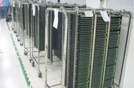
Method 2: Use a furnace carrier/carrier
The furnace carrier can be designed such that the ribs just support the position of the heavier parts, so that the heavier parts are not easy to fall during the second reflow soldering. However, the cost of the furnace carrier is not cheap, and the total number of carriers must be greater than the length of the reflow oven, that is to say, how many boards are walking in the reflow oven at the same time, and buffering should be added. (buffer) and spare parts, all add up to not 30, there are also 20, and there may be more, which is not expensive.
In addition, because the furnace carrier needs to withstand the high temperature of repeated reflow soldering many times, it is generally made of metal material or special high-temperature resistant plastic. There is also a special reminder that using Carrier will require an extra labor cost. Putting the board on the carrier requires labor, and the recycling and reuse of the vehicle also requires labor.
Secondly, the use of the carrier may cause the risk of deterioration of the tin melting condition, because the furnace carrier is usually made of metal, and the area is large and easy to absorb heat, which will cause the risk of difficulty in temperature rise, so when you adjust the furnace temperature, you must It must be measured together with the furnace carrier, and the carrier should try to steal the unused meat, as long as the carrier is sufficiently supported and not deformed as a principle.
Method three, adjust the temperature difference between the upper and lower furnaces of the reflow furnace
The reflow furnace can usually control the upper and lower furnace temperature. The early electronic parts are still in the age of 1206. When we adjust the reflow furnace, the lower furnace temperature bar is usually 5~10°C lower than the upper furnace temperature., The purpose is to hope that when the second side is reflowed, the parts that have been welded on the first side will not fall due to remelting the tin, but now most SMT engineers do not adjust the furnace temperature in this way, because the parts are very small. There is no risk of falling.
With the above requirements, it is certain that the large parts on the first side will fall when reflowed on the second side, but if it is a large and heavy part of the connector, even if the temperature difference between the upper and lower furnaces is adjusted, the part cannot be reached. Not required to drop.
Therefore, adjusting the upper and lower temperature difference of the reflow furnace is only useful for small parts, that is, it is effective when it is found that some parts will fall, and some parts will not fall. If all parts are dropped, this method is invalid.
Method four, go back and re-welding after use (machine welding, manual welding)
Calculate the cost of post-re-welding and the cost of falling parts. Compare the cost-effectiveness. Sometimes blindly pursuing automation when the time is not ripe may not save costs. It is better to compare and calculate whether the calculation is cost-effective. .
In addition to manual welding for post-re-welding, robot welding can also be considered. After all, there are doubts about the quality of manual welding. (PCB manufacturer)