The trend of changing the way we do business today through the right communication tools that are highly suitable for your business purposes has now become one of the mantras of success for every vertical business. As new models are launched on smartphones, tablets, laptops and other communication devices every other day, the printed circuit board industry has taken a step forward to provide the best electronic and design solutions to improve the communication tool manufacturing process The requirements make it very simple. Manufacturers propose new technological innovations. With this, microwave and radio frequency printed circuit boards have become an excellent part of manufacturing major electronic devices. This article will delve into the technical details of microwave PCBs or radio frequency printed circuit boards, while considering new PCB manufacturing methods to obtain precise electronic and design solutions that can achieve high-speed signal speeds in electronic instruments.
1. The new era of modernization of communication equipment and tools used in daily business processes marks a high expansion of the development of all leading industries. By using radio frequency PCB or microwave PCB, PCB experts and manufacturers have launched a new and innovative product series on the global market. Microwave PCB has become a professional field, which can capture and find the exact needs of electronic manufacturers. In addition, the RF PCB is a rugged electronic design with high stability when the amplitude, current level, and voltage change according to the climate. Let us first understand the details of RF and microwave PCB!
2. The term microwave circuit is derived from the Greek word "micros", which means very little or very small. In microwave or radio frequency circuits, the wavelength is small compared to physical changes in the circuit and component size changes that cause high-speed signals. It has a laminated material with mechanical, electrical and thermal properties not found in FR4 materials. This type of PCB was introduced to the market in the 20th century. With this, many new microwave circuit methods are the output of research and development, including microwave integrated circuits (MIC), waveguide and coaxial technology, monolithic microwave integrated circuits (MMIC), and so on.

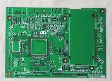
3. The printed circuit board used to control the communication signal, which is mainly used for avionics and wireless circuit applications in medium and high frequency mode operation, is called radio frequency PCB or microwave PCB. RF circuits are used in specific feature-rich PCB layouts, and are best installed in everything from military radars to laptops, mobile phones, and so on.
4. Many people are confused about the difference between ordinary printed circuit boards and microwave PCBs! The main difference between the two lies in the physical and electrical characteristics of the dielectric board. Generally, the radio frequency range is 500 MHz-2 GHz. If the layout is higher than 100 MHz is considered as RF PCB, the layout higher than 2 GHz will be considered as the microwave frequency range.
To make it easier to understand, it is important to consider how signal speed works. High-performance microwave PCBs?
5. PCB manufacturers should consider important PCB manufacturing methods that enable devices with high-performance output, so as to provide the best modification of customized functions in microwave PCBs or RF printed circuit boards. The material used in PCB manufacturing should be an element with specific properties of dielectric constant (ER), coefficient of thermal expansion (CET) and loss tangent. This allows the signal to accelerate as it passes through the PCB at a low impedance rate. It even makes printed circuit boards with high stability, resistance to extreme temperatures and climates, and precise placement of fine-pitch components.
Multilayer PCBs are mainly used for such PCB applications.
Low impedance ground planes work well in RF and microwave PCBs.
To avoid crosstalk, RF signal lines should be placed at the same distance and far apart.
Thermal management proves that the copper shape and flatness are the best.
Have a solid ground plane to minimize inductance.
6. Other important considerations involve the types of microwave packaging technology, which are mainly of two types (namely, circuit card components and hybrid circuits). In order to obtain bulletproof reliability, the packaging of hybrid modules has proven to be effective, and it also has high applications in the military and aerospace industries. And circuit card components are most suitable for purchasing cost-effective and quality solutions. In addition, before starting a PCB project, one must learn more about the basics of RF and microwave PCBs.
7. There are many other important aspects to consider in PCB manufacturing of RF or microwave PCBs. To start any type of PCB project, whether it is a new task or PCB rework, it is very important to get advice from PCB experts to control costs and time to keep the PCB project at the forefront.