In the input data of the PCB Layout task, it mainly includes the schematic diagram, structural element diagram, design requirements, plan completion schedule and so on. In this article, we mainly come to understand the structural element diagram.
Structural element diagram
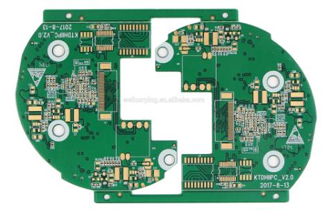
It specifies the size and shape of the PCB board, and the location requirements of special devices (such as interface connectors, mounting holes, structure forbidden areas, device height restrictions, etc.), which are generally provided by the structural engineer, or can be exported from the PCB file in the reverse direction.
Reminder: The location of the device required by the structural element diagram needs to be prioritized.
What needs to be marked in the structural element diagram
The content that needs to be accurately marked on the structural element map includes the following aspects:
(1) PCB thickness range;

(2) PCB board outline dimensions (including chamfering, concave-convex grooves, internal openings, etc. required by the structure);
(3) Positioning of connectivity devices (including LED, network port/serial port, optical port, coaxial connector, power switch, power socket, reset switch, backplane connector, guide sleeve/guide pin, etc. and other R&D deems necessary Marked devices);
(4) The location of PCB mounting holes, the requirements of the aperture, the height limit of the device and the prohibition requirements (the area where the placement of the device or the wiring is prohibited has an obvious sign and a corresponding text description);
(5) The hole position, aperture requirements and the requirements of the forbidden area in the installation of the handle bar (the area where the device is forbidden to be placed or the area where the wiring is forbidden has obvious signs and corresponding text descriptions);
(6) Requirements for the forbidden area where the handle bar touches the PCB surface after assembly;
(7) The plug-in PCB needs to mark the height range of the upper and lower slots;
(8) The TOP & BOTTOM of PCB needs to mark or explain the height requirements for devices that have height restrictions.
The importance of structural element maps
When the PCB is laid out, it is necessary to carry out the device layout and set the forbidden area according to the structural element diagram.
(1) According to the structural element diagram, place the components that need to be positioned, such as connectors, mounting holes, and indicator lights, and give these components non-movable attributes, and carry out dimensions.
(2) According to the structural element diagram and the special requirements of certain devices, set up prohibited wiring areas and prohibited layout areas.
Logo description of structural element diagram
The structural element diagrams imported into the PCB generally have three views: front view, side view, and back view.
(1) Front view: generally marked with the length and width of the PCB, the coordinates of each structural device, the height limit of the front device, and the forbidden area.
(2) Side view: marked with PCB thickness and size information.
(3) Rear view: marked with the height limit on the back and the requirements of the forbidden area.
Reminder: Before importing into the PCB design software, you need to ensure that the structural element drawing file is the latest version.