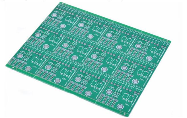
The so-called copper coating uses the unused space on the PCB as a reference surface and then fills it with solid copper. These copper areas are also called copper fills. The significance of the copper cladding layer is to reduce the impedance of the ground wire and improve the anti-interference ability; reduce the voltage drop and improve the efficiency of the power supply; connecting the ground wire also reduces the loop area. In addition, in order to solder the PCB as much as possible, most PCB manufacturers also require PCB designers to fill the open area of the PCB with copper or grid-like ground wires. If the copper is not properly handled, then if it is not worth the loss, is the copper cladding "better than the disadvantage" or "does more harm than good"?
Everyone knows that at high frequencies, the distributed capacitance of the printed circuit board wiring will work. When the length is greater than 1/20 of the corresponding wavelength of the noise frequency, an antenna effect will occur and noise will be emitted through the wiring. If the copper in the PCB is grounded badly, then copper is a tool for noise transmission. Therefore, in a high-frequency circuit, do not assume that a place on the ground is connected to the ground. This is the reason. Make sure to punch holes in the wiring with a pitch less than λ/20, and "good ground" with the ground plane of the multilayer board. If the copper coating is properly treated, the copper cladding not only has an increased current, but also plays a dual role of shielding interference.

Two basic methods of covering copper. This is a large area of copper and grid copper. People often require large areas of copper to be good, or copper mesh to be good. It is not easy to generalize. Why? The large-area copper cladding has the dual functions of increasing current and shielding. However, if the large-area copper is wave soldered, the board may tilt upward or even foam. Therefore, for large-area copper, several slots are generally opened to relieve the blistering of the copper foil. The simple mesh copper is mainly for shielding, and the effect of increasing current is reduced. From the perspective of heat dissipation, the mesh is beneficial ( It reduces the heating surface of copper) and acts as an electromagnetic shield. However, it should be noted that the grid is composed of traces in staggered directions. We know that for the circuit, the width of the trace has an "electrical length" (the actual size is separated) corresponding to the operating frequency of the circuit board. The digital frequency corresponding to the working frequency can be obtained, especially related books. When the operating frequency is not very high, perhaps the effect of the grid lines is not very obvious. Once the electrical length matches the operating frequency, it will be very bad, and you will find that the circuit does not work at all, and signals that interfere with the operation of the system are transmitted everywhere. Therefore, for colleagues who use the power grid, it is recommended to choose work according to the design of the circuit board, and do not take anything. Therefore, high-frequency circuits can resist the interference of multi-purpose power grids, and low-frequency circuits with large current circuits are usually used for copper plating.
Having said that, in the copper cladding layer, in order to make the copper achieve our expected results, what issues should be paid attention to in the copper cladding layer:
1. If the PCB has more grounds, there are SGND, AGND, GND, etc. Depending on the position of the PCB board, the most important "ground" is used as a reference for separating the copper, and the reference for digital grounding and analog grounding is to separate the copper wiring. At the same time, in the copper coating Before, first increase the corresponding power connection: 5.0V, 3.3V, etc., so as to form a multi-deformation structure with a variety of different shapes.
2. For single-point connections to different locations, the method is to connect via 0 ohm resistors or magnetic beads or inductors.
3. The copper near the crystal oscillator, the crystal oscillator in the circuit is a high-frequency emission source, the method is to surround the crystal copper, and then the crystal shell is grounded separately
4. The problem of islands (dead zones), if it feels good, it won't cost much to define a hole in the hole.
5. At the beginning of the wiring, the grounding wire should be treated equally. When wiring the wires, the ground wire should be good. It is impossible to rely on copper to add through holes to eliminate ground pins. The effect is very bad.
6. It is best not to have sharp corners ('180 degrees') on the circuit board, because from an electromagnetic point of view, this constitutes a transmitting antenna! For other things that are always valid, it's just big or small. I recommend using arc edges.
7. The wiring of the middle layer of the multilayer board is not covered with copper. Because it is difficult for you to "good ground" this kind of copper.
8. The metal inside the device, such as metal radiator, metal reinforcement tape, etc., must be "good grounding".
9. The heat-dissipating metal block of the three-terminal regulator must be well grounded. The grounding barrier near the crystal must be well grounded.
In short: the copper on the PCB circuit board, if the grounding problem is dealt with, it must be'profits outweigh the disadvantages, it can reduce the return area of the signal line, and reduce the signal's external electromagnetic interference.