There are four types of PCB schematics: schematics, block diagrams, assembly drawings and printed circuit boards.
1. Schematic diagram, also known as "electrical schematic diagram". The schematic diagram directly reflects the structure and working principle of electronic circuits, and is generally used for circuit design and analysis. When analyzing the circuit, you can understand the actual working principle of the circuit by identifying the symbols of the various circuit components drawn in the diagram and the connections between them. The schematic diagram is a tool that reflects the working of electronic circuits.

2. Block diagram. A block diagram is a circuit diagram that uses a block diagram and wires to represent the working principle and composition of the circuit. Basically, this is also a schematic diagram, but in this picture, there are almost no symbols other than boxes and wires. The main difference between the above schematic diagram and the schematic diagram is that all components of the circuit and their connection methods are drawn in detail. The schematic diagram simply divides the circuit into multiple parts by function, describes each part as a box, adds a simple text description to the box, and uses connecting lines between modules (sometimes with arrows). The relationship between the boxes. Therefore, the block diagram can only reflect the general working principle of the circuit. In addition to a detailed description of the working principle of the circuit, it can also be used as a basis for collecting components and circuit production.
3. Assembly drawing. This is the circuit assembly drawing. The symbols in the figure are usually the physical outlines of circuit components. As long as we follow the drawings, we can assemble the circuit by connecting some circuit components. This circuit diagram is usually used by beginners. Depending on the assembly template, the assembly drawing is different.
The use of electronic products is mainly the printed circuit board (pcb) described below, so PCB is the main form of assembly drawing. In the early days of learning electronic knowledge, in order to get in touch with electronic technology earlier, we chose the threaded plate as the basic installation template, so the installation drawing will become another mode.

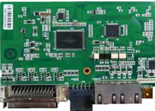
4. Printed board diagram. The full name of the printed circuit board diagram is "printed circuit board diagram" or "printed circuit board diagram". It belongs to the same circuit diagram as the assembly drawing and is used for the assembly of the actual circuit.
The printed circuit board is an insulating board covered with a layer of metal foil. Then the circuit does not need to corrode the metal foil. The circuit components are connected between the rest of the metal foil, and then the circuit components are mounted on the insulating board using the remaining metal foil.
The connection between the boards. Since one or both sides of the printed circuit board are plated with copper, the printed circuit board is also called "copper board". The component distribution on the printed circuit board is usually very different from the component distribution on the schematic.
This is mainly because in the design of printed circuit boards, the main consideration is the distribution and connection of components, and factors such as component volume, heat dissipation, anti-interference, and anti-coupling need to be considered.
A printed circuit board designed with these factors is difficult to match the schematic visually. In fact, it can perform circuit functions better.
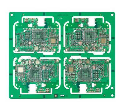
With the development of science and technology, the production technology of printed circuit boards (PCB) has been greatly developed. In addition to single and double panels, there are many panels that are widely used in daily life, industrial production, national defense construction, aerospace and other fields.
In the above four circuit diagrams, the electrical schematic diagram is the most common and the most important. The schematic diagram is easy to understand, basic understanding of circuit principles, drawing block diagrams, design assembly drawings and printed circuit board diagrams. It is also very convenient to master electrical schematic diagrams and to maintain and design electrical equipment.
Therefore, the key is to master the schematic diagram.