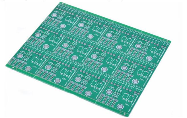
For the new PCB board that has just been taken back, we must first roughly observe whether there are problems on the board, such as whether there are obvious cracks, whether there are short circuits, open circuits, etc.
If necessary, check whether the resistance between the power supply and the ground wire is large enough. Then it's time to install the components. Independent modules, if you are not sure that they are working properly, it is best not to install all of them, but to install part by part (for relatively small circuits, you can install them all at once), so that it is easy to determine the fault range. Avoid having trouble getting started when you encounter problems.
Generally speaking, you can install the power supply first, and then power on to check whether the output voltage of the power supply is normal. If you do not have much confidence when powering up (even if you are sure, it is recommended that you add a fuse, just in case), consider using an adjustable regulated power supply with current limiting function. Preset the overcurrent protection current first, then slowly increase the voltage value of the regulated power supply, and monitor the input current, input voltage, and output voltage. If there is no overcurrent protection and other problems during the upward adjustment, and the output voltage has reached normal, the power supply is OK.
Otherwise, disconnect the power supply, find the fault point, and repeat the above steps until the power supply is normal.
Next, install other modules gradually. After each module is installed, power on and test it. When power on, follow the above steps to avoid over-current caused by design errors and/or installation errors and burn out components.

PCB circuit board welding and debugging methods, and the methods to find faults are generally as follows:
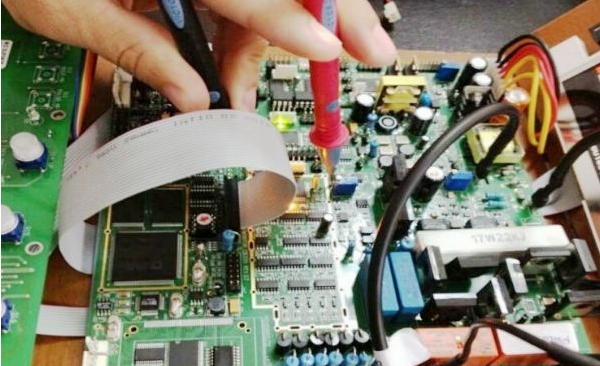
1. Measure voltage method. The first thing to confirm is whether the voltage of the power supply pins of each chip is normal, and then check whether the various reference voltages are normal, and whether the working voltage of each point is normal. For example, when a general silicon transistor is turned on, the BE junction voltage is about 0.7V, while the CE junction voltage is about 0.3V or less. If the BE junction voltage of a transistor is greater than 0.7V (except for special transistors, such as Darlington, etc.), it may be that the BE junction is open.
2. Signal injection method. Add the signal source to the input terminal, and then measure the waveform of each point in turn to see if it is normal to find the fault point. Sometimes we also use simpler methods, such as holding a tweezers with our hands, and touching the input terminals of all levels to see if the output terminals respond. This is often used in amplifying circuits such as audio and video (but note that the hot bottom plate This method cannot be used for circuits with high voltage or high voltage circuits, otherwise it may cause electric shock). If there is no response to the previous level, but there is a response to the next level, it means that the problem lies in the previous level and should be checked.
3. Of course, there are many other ways to find fault points, such as watching, listening, smelling, touching, etc. "Seeing" is to see if there are any obvious mechanical damages to the components, such as cracks, burns, and deformation.
"Listening" is to listen to whether the working sound is normal, for example, something that shouldn't be ringing is ringing, the place that should be ringing is not ringing, or the sound is abnormal.
PCB soldering "smell" is to check whether there is any peculiar smell, such as the smell of burning, the smell of capacitor electrolyte, etc. For an experienced electronic repairer, it is very sensitive to these smells.
"Touching" is to test whether the temperature of the device is normal by hand, for example, it is too hot or too cold. Some power devices will heat up when they work. If they are cold to the touch, it can basically be judged that they are not working. But if the place that shouldn't be hot is hot or the place that should be hot is too hot, that won't work either. For general power transistors, voltage regulator chips, etc., it is completely fine to work below 70 degrees. What is the concept of 70 degrees? If you press your hand up, you can hold it for more than three seconds, it means that the temperature is below 70 degrees (note that you must touch it tentatively first, and don't burn your hands).