PCB assembly preparation is mainly to prepare various process documents used in circuit assembly
PCB assembly preparation is mainly to prepare various process documents used in circuit assembly. It mainly includes product process documents and working documents needed to organize production. The former is divided into two categories: one is based on projection diagrams, used to illustrate product processing and assembly requirements, parts, printed circuit board assembly drawings, and so on. The other is based on graphical symbols to describe the design content of the circuit. Such as system diagrams, block diagrams, circuit diagrams, wiring diagrams, etc.
1. Block Diagram
A block diagram is an annotated diagram that outlines the basic components, interrelationships, and main characteristics of electronic products. The "box" in the block diagram represents a functional block, and the "line" represents the signal route or sequence through the circuit.

2. Circuit diagram
Circuit schematic diagram, also known as electrical schematic diagram and electronic circuit diagram, is a drawing for the arrangement of various parts in the product. The circuit schematic diagram does not consider the actual location of the components, and does not represent the shape and size of each component. It is drawn on the basis of the circuit block diagram and is the basis for design, wiring, product performance analysis and maintenance.
The drawing of the circuit schematic diagram requires accurate, beautiful and reasonable layout. The input signal is usually on the left, the output signal is on the right, and the symbols of the components meet the requirements of the drawing. The same component symbols are numbered from left to right or top to bottom. The wires between the components in the circuit diagram represent wires, and the junctions of two or more wires are marked with (solid dots). It means that two or more wires should cross but not connect. In the circuit diagram, the "floor" is represented by the symbol "X", and all "grounds" must be connected by wires. Circuit schematic
3. List of supporting materials
The supporting material list is a list of the names and specifications of materials required for electronic products. Procurement and assembly quantity and no equipment code table.
4. Schematic diagram of parts
The component schematic diagram includes the printed circuit board assembly diagram and the schematic diagram of the chassis panel.
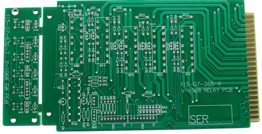
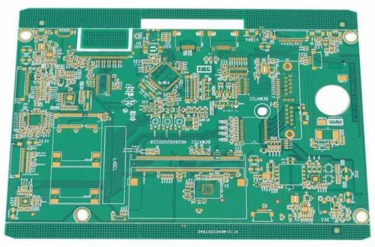
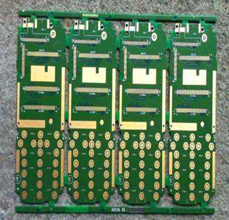
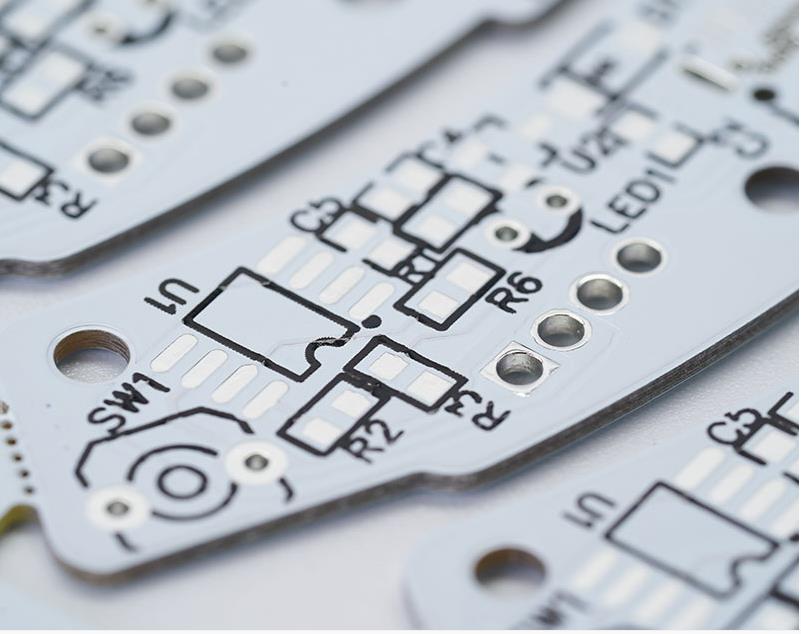
(1) Printed circuit board assembly drawing
The PCB assembly drawing is a graphic showing the connection relationship between the components and the PCB. Suitable for assembly and welding of PCB process drawings.
The schematic circuit diagram and the actual circuit board are connected through the PCB assembly drawing. It is an indispensable diagram in electronic assembly and maintenance. It is sometimes used for testing and repairs to find the location of components.
(2) Schematic diagram of the chassis panel
The schematic diagram of the chassis panel is a schematic diagram of the installation of various components in the chassis panel. Since the superheterodyne radio is a simple electronic product, there is no schematic diagram of the chassis panel.
For complex electronic products, the process documents also include wiring diagrams and wiring tables, which are not explained here.
5. Brushed
For the connection of uncomplicated electronic PCB products, there is no need to tie wires, but for complex products, due to the large number of connecting wires, the connection is complicated, and it is difficult to find or affect the appearance, generally it is required to draw wires and tie wires.
6. Assembly drawing of the whole machine
The assembly drawing of the whole machine indicates the assembly position and overall appearance of the parts.