Simply speaking, it is to put the integrated channel bare chips PCB consumed by the manufacturer on a bearing substrate, lead the pins in, and then change the flow packaging. It can play the role of cover. In addition, there is no shell that can only flow and seal the chip, and its electrothermal function can be strengthened. Because it plays an extremely important role in CPU and other large-scale integration channels.
Dual inline
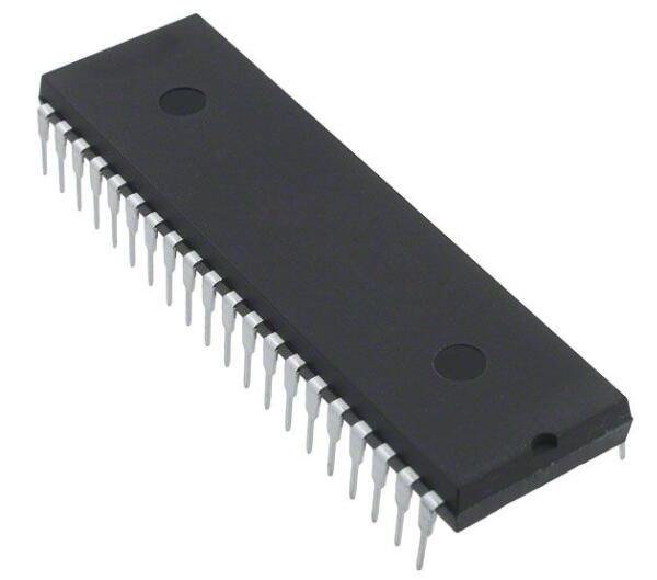
It refers to the integrated path chip packaged in dual in-line mode. The vast majority of small and medium-sized integrated paths adopt this packaging mode, and the number of pins does not exceed 100. The encapsulated CPU chip PCB has two rows of pins, which need to be pulled out to the chip socket stored in dip structure. It can also be indirectly inserted into the access board with the opposite number of welding holes and how many are displayed to stop riveting. When the chip of dip package is being plugged from the chip socket, you should be especially careful to avoid protecting the pin. Dip packaging construction methods include multi-layer ceramic dual in-line dip, single-layer ceramic dual in-line dip, lead frame dip (including glass ceramic sealing type, plastic packaging construction type, ceramic low melting glass packaging type), etc. Dip is the most improved plug-in package, and its application scope includes specification, logic, IC, memory and microcomputer access.

DIP packaging
Characteristic:
It is suitable for piercing and riveting on PCB (printed circuit board) and easy to operate.
The ratio between the total core area and the package area is big, so the volume is also bigger.
The earliest 4004, 8008, 8086, 8088 and other CPUs adopted dip package, which can be inserted into the slot on the motherboard or riveted on the motherboard through two rows of pins.
During the period when external memory particles are indirectly inserted on the motherboard, dip packaging has been very popular. Dip has another derivative form sdip (shrink dip), which is six times higher than the pin density of dip.
Abnormal:
However, because its package area and thickness are relatively large, and the pins are simple to be protected in the plug-in process, the reliability is poor. At the same time, due to the reaction of the process, the number of pins does not exceed 100. With the high and low integration of the external CPU, dip packaging soon joined the historical stage. As long as you can see their "footprints" on the old VGA / SVGA graphics card or BIOS chip.
PQFP / PFP package
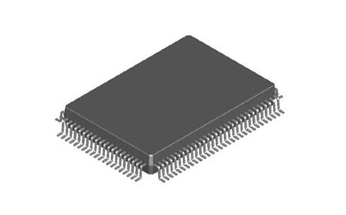
There are pins everywhere in the chip of PQFP package. The spacing between pins is very small and the pins are very thin. This packaging method is adopted for normal large-scale or hybrid integrated channels, and the number of pins is normally above 100.
The chip packaged in this way must adopt SMT (nominal disassembly skill) to rivet the chip PCB to the motherboard. The chip adopting SMT device does not need to punch holes on the motherboard. Normally, the motherboard nominally has envisaged solder joints corresponding to the pins. The riveting with the motherboard can be completed by aligning each pin of the chip with the corresponding solder joint. The chip packaged in PFP form is fundamentally opposite to PQFP form. The only difference is that PQFP is normally square, while PFP can be either square or rectangular.

PQFP packaging
Characteristic:
PQFP packaging is practical for SMT nominal device wiring, suitable for high-frequency application. It has the advantages of easy operation, high reliability, childish technology and high price.
Abnormal:
The deficiency of PQFP packaging is also obvious. Because the chip side length is infinite, the pin units in the form of PQFP packaging are helpless to increase, which restricts the stagnation of graphics deceleration chip. Parallel pins are also a stumbling block to the stagnation of PQFP package connection, because when the parallel pins are transmitting high-frequency signals, there will be a fixed capacity, which will lead to high-frequency noise signals. In addition, the long pins simply attract this disturbing music, just like the ground wires of radio, how many hundreds of "ground wires" disturb each other, The chip encapsulated by PQFP is difficult to work under high frequency. Therefore, the core area / package area ratio of PQFP package is too small, which also restricts the stagnation of PQFP package. In the early 1990s, PQFP was eliminated by the market after all with the childish skills.
PGA (pin grid array) package
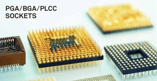
There are multiple phased array pins inside and outside the PGA encapsulated chip PCB. Each phased array pin is displayed at regular intervals along the four distances of the chip. It can be surrounded by 2 ~ 5 circles according to the number of pins. When installing the device, pull the chip out of the special PGA socket. In order to make the CPU more convenient for device and assembly, a ZIF CPU socket has emerged from the 486 chip, which is specially used to satisfy the request of PGA encapsulated CPU on device and assembly. This skill is normally used in places where plugging operations are relatively frequent.

PGA packaging
Characteristic:
1. The plugging operation is more convenient and reliable.
2. It can adapt to higher frequency.
Ball grid array package
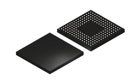
With the retrogression of integration skills, the improvement of facilities and the application of deep Asimi skills, LSI, VLSI and ULSI have emerged one after another, and the integration of silicon single chip has been improved. The requirements for integrated path packaging have become more and more stringent, the number of I / O pins has increased sharply, and the power consumption has also increased. When the frequency of IC exceeds 100MHz, the conservative packaging form can produce a scene called "crosstalk", Moreover, when the number of IC pins is greater than 208 pin, the conservative packaging form is difficult. In order to meet the stagnant demand, a new type of ball grid array packaging is added to the original packaging type.
The I / O terminals of BGA package are distributed on the package in an array of circular or cylindrical solder joints

BGA packaging
Characteristic:
1. Although the number of I / O pins increases, the pin distance is much greater than QFP, which improves the disassembly scrap rate.
2. Although its power consumption increases, BGA can be riveted by controllable falling chip method and C4 riveting, which can improve its electrothermal function.
3. The thickness ratio is more than 1 / 2 smaller than QFP, and the component is more than 3 / 4 heavier.
4. The parasitic parameters are reduced, the signal transmission is less early, and the application frequency is greatly improved.
5. Coplanar riveting can be used for disassembly, with high reliability.
6. BGA packaging is still the same as QFP and PGA, occupying too much area of base cabinet.
In conclusion, rare chip PCB types: Dual inline, PQFP / PFP package, PGA (pin grid array) package, Ball grid array package, I / O terminals of BGA package. At present, as far as I know, that's all. But if you have other different suggestions and ideas, you are welcome to add them. Ipcb always welcomes you to technical communication and exchange.