Reasons for the failure of the PCB circuit board:
According to relevant data reports, up to 78% of hardware failures are caused by poor PCB soldering processing.

In the case of hardware failure, engineers are willing to spend a lot of time and energy in the debugging and analysis of the prototype, which delays the progress of the project. If they can't find the bad reason, they will also habitually think that the problem lies in the design of the software and hardware circuits. When actually doing hardware debugging, engineers often consider many high-level potential incentives, but are unwilling to doubt the most obvious and easy to make mistakes:
Case 1: A large number of decoupling capacitors are densely distributed next to the CPU power supply. Due to the excess solder PCB soldering process during the soldering process, a certain electrical PCB capacitor is short-circuited. As a result, hardware engineers have to troubleshoot the cause of the short-circuit one by one, which takes a lot of time.
Case 2: Due to the virtual welding of a certain signal in the DDR high-speed signal part, the system seems to work normally when transmitting ordinary small data volume, but when doing burst operations with large data volume, such as operating system loading, high-definition movie playback,, Will often report errors. And it is often mistaken for software reasons, and software engineers look at the code to no avail.
Case three, high-speed signal interface connector, due to a certain signal false welding, PCB welding processing causes the system to work at a lower level
Case 5, due to the poor welding of the inductor part, the PWM dimming function of the LED fails, and the PCB welding process
Engineers spend a lot of time confirming whether it is a software or hardware problem.
Case Four: Due to improper time and temperature control during welding, the plastic structure inside the connector such as LCD and USB melted and deformed due to high temperature, causing a certain signal to be accidentally disconnected, so that the LCD did not display, the USB did not communicate, and was mistaken Thought it was a software driver problem.
These problems seem simple, but there are also many welding details and steps that are pieced together, and these links are also interlocked with each other, and any error in any link will cause problems. Therefore, in the process of hardware debugging, it is recommended that engineers first observe the welding quality of your prototype.
1. Is the material correct?
2. Is the pin position correct?
3. Whether there is empty welding, virtual welding, or even tin
4. Is the solder paste full and reflective after the furnace?
5. Does the structural part of the connector melt at high temperature?
6. Does the chip position correspond to the silk screen?
After inspecting the above "simple and obvious" items, PCB welding process, and then focus on those "advanced" problems! This is the smart choice.
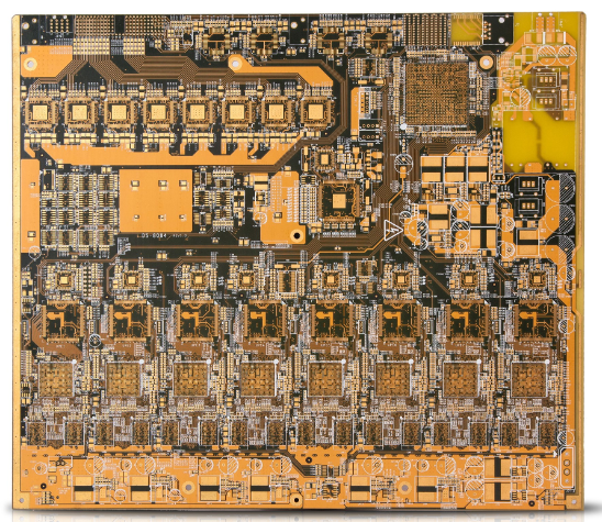
There are two different processes in the production of circuit boards, positive film and negative film. The negative film board is charged after the copper is sinked. The main function of the board power is to increase the thickness of the copper on the inner wall of the hole and increase the thickness of the circuit copper on the board to achieve The customer’s requirements mainly include the micro-etching section, the pickling section, the copper-plating section and the various washing sections; the positive film is the outer layer of the image development, and the role of the image The copper surface exposed after development is plated with a layer of tin to protect the required circuits from being etched in the subsequent alkaline etching
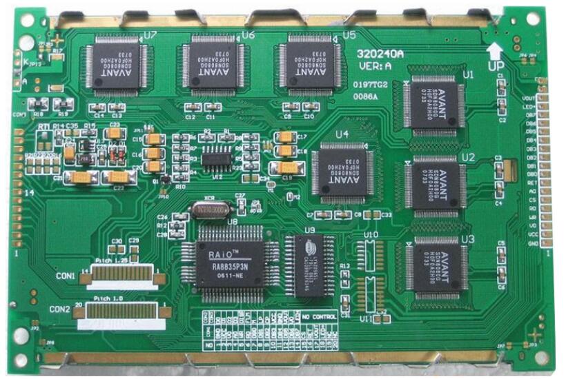
There is no difference between a circuit board and a circuit board, and they are essentially the same.
The circuit board is just a designed and manufactured substrate, and the circuit board refers to the circuit board on which various components have been installed.
The names of the circuit boards are: circuit boards, PCB board, aluminum substrates, high-frequency board, PCBs, ultra-thin circuit boards, ultra-thin circuit boards, printed (copper etching technology) circuit boards, etc. The circuit board makes the circuit miniaturized and intuitive, which plays an important role in the mass production of fixed circuits and optimizing the layout of electrical appliances.
Circuit board: On an insulating substrate, a printed board that connects wires from point to point is formed according to a predetermined design, but there is no printed component.
Circuit board: On an insulating base material, a printed board that connects wires from point to point and prints components according to a predetermined design.
A circuit board is the kind with electronic components. The circuit board is the kind of PCB board. The circuit board is the most contacted without electronic components, and the main board is the circuit board.