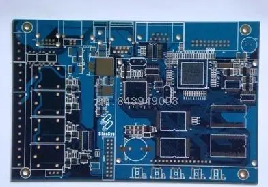
In many cases, SMT processing plants have to race against time, especially when the patch is fast proofed, customers generally do not give too much time. Because PCBA patch processing customers want to save the time of proofing to the greatest extent, and try to reduce the production cycle. The time saved is used for testing, optimizing plans, and evaluating production costs.
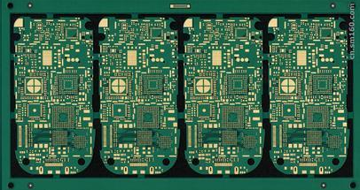
At present, most of the products produced by the patch processing plant are large-scale, so the coordinate file of the PCB can be used directly for rapid programming during programming, without the need to separately locate the coordinate position of each component. When the coordinate file of the PCB is obtained, the X and axis parameters equivalent to the patch processing file have been determined, and only the axis parameters of the patch file need to be determined.

Only familiarity with programming can make the product go online faster, the specific steps are as follows:
(1) Export the Generales pick and place files from the PCB drawing software and copy it to the industrial computer of the chip machine.
(2) In the "Guide" tab, click "Open Import File", select the file copied to the industrial computer, and click the "Open" button.
(3) After opening, just keep Designator, MidX, MidY, Solation, and change the four names to position, X coordinate, Y coordinate, and angle respectively.
(4) There are two ways to specify MARKI and MARK2: manually specify MARK and system specify MARK. 1. Manually specify MARK: Remember the coordinates of two points that are diagonal to each other in the PCB drawing software, fill in the recorded two sets of coordinates into the MARK coordinates and MARK2 coordinates below, click the "Generate" button, and then move When the MARK camera finds the MARK point, click the "Set MARKI Coordinates" button, move the MARK camera again to find the MARK2 point, and click the "Generate MARK2 Coordinates" button.
2. System designated MARK: After selection, the PCB system will automatically select two MARK points from all coordinates, among which
MARKI is green, MARK2 is blue, click the "Generate" button, then move the MARK camera to find the point of the green bar, click "Set MARKI coordinates", move the MARK camera again to find the point of the blue bar, click "Set MARK2 coordinates" button.
(5) After setting MARK2, it will automatically jump to the "Installation" tab interface, and then specify the component location and nozzle number, right-click the mouse and select the "Search component location" option, and enter according to the exported BOM form The position number of the component.
After clicking the "OK" button, on the blue component that appears, click the right mouse button - select "Associated PCB Components" - select the PCB components corresponding to these mounting positions and click the right mouse button again - select "Suck Nozzle sort" - select the nozzles that these components need to use.
(6) After all settings are complete, click the "Verify Correctly" button - "Save" button.
(7) Operation.