At the beginning of the 20th century, before the advent of printed circuit boards, the interconnection between electronic components relied on the direct connection of wires to form a complete circuit. In order to simplify the production of electronic equipment, reduce wiring between electronic components, and reduce production costs, people began to delve into the method of replacing wiring with printing.
In 1903, the German inventor Albert Hanson described a flat foil conductor laminated on an insulating board in multiple layers. Thomas Edison (Thomas Edison) experimented with the chemical method of plating conductors on linen paper in 1904.
In 1913, Arthur Berry applied for a patent for printing and etching methods in the UK.
In 1927, Charles Ducas of the United States applied for a patent for a method of electroplating circuit patterns.
In 1936, Austrian Paul Eisler (Paul Eisler) invented the foil technology in the UK, using a printed circuit board in a radio device. Paul Eisler's approach is most similar to today's PCB printed circuit boards.
In 1941, the German magnetically affected mines used multilayer printed circuits.
In 1943, the United States applied PCB printed circuit board technology to military radios.
In 1948, the United States used PCB printed circuit boards for commercial purposes.
Since the mid-1950s, printed circuit boards have been widely used.
Paul-eisler-by-maurice-hubert-1
Paul Eisler's first radio uses a printed circuit chassis and antenna coil

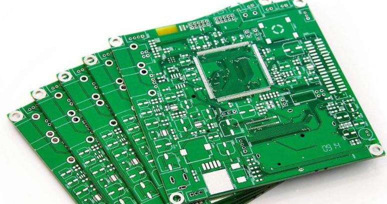
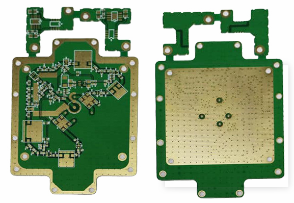
PCB development
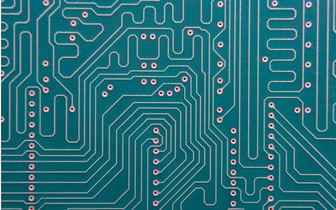
Printed boards have developed from single-layer to double-sided, multi-layer and flexible, and still maintain their respective development trends. Due to the continuous development of high precision, high density and high reliability, continuous reduction in size, cost reduction, and performance improvement, the printed circuit board will still maintain a strong vitality in the future development of electronic equipment.
The domestic and foreign discussions on the future development trends of printed board manufacturing technology are basically the same, that is, to high density, high precision, fine aperture, fine wire, fine pitch, high reliability, multilayer, high-speed transmission, light weight, The development of thin type, in the production, at the same time, to increase productivity, reduce costs, reduce pollution, and adapt to the development of multi-variety, small-batch production. The technical development level of the printed circuit is generally represented by the line width, aperture, and plate thickness/aperture ratio on the printed board.
Four inspection methods for circuit board repair
1. Observation and testing
When inspecting a circuit board to be repaired, we must first visually inspect the appearance to ensure that it will not cause secondary damage when it is energized. If there is a general external problem, we can directly see the problem with the circuit board and deal with it.
Man-made causes
The corners of the circuit board, whether the chip is broken or deformed;
Whether the direction of the chip with socket is correct;
Whether the chip socket is forcibly broken;
Whether the circuit board with short-circuit terminal is inserted incorrectly.
Burning reason
Whether the resistors, capacitors, and diodes are burnt;
Whether the integrated circuit has bulges, cracks, burns, or blackening;
Whether the circuit board traces are peeled or burnt;
Whether the sinking copper hole is out of the pad;
Whether the fuse and thermistor are burned or broken.
2. Static detection
If no problems are found in the circuit board to be repaired through observation and inspection, then it is necessary to use a universal meter to measure the main components and key points for troubleshooting.
Whether the power supply and ground are short-circuited
Use a multimeter and a 5V power supply chip to measure two points on the diagonal to observe if there is a short circuit.
Is the diode working properly
Use a multimeter to test the positive and negative poles of the diode and observe whether the diode is broken down due to excessive current.
Whether the capacitor is short circuit or open circuit
Use a multimeter to measure the capacitance to see if there is a short circuit or open circuit. If so, respectively, check whether there is a problem with the component itself or a problem with the connected circuit.
Whether the components meet the logic performance
Use a multimeter to detect integrated circuits, transistors, resistances, etc., and check the resistance row of the bus structure.
3. Live detection
Mainly used for PCB manufacturers, manufacturers generally use a general debugging platform to test the circuit board, through observation and static testing to subdivide the problem, and finally lock to the problematic component. If the problem is not resolved, it needs to be checked through live detection.
Whether the components are too hot
Power on the circuit board, check whether the temperature of each chip is normal, replace if the temperature is too high, and check whether it is normal.
Whether the PCB gate circuit conforms to the logical relationship
Measure the circuit board gate circuit with an oscilloscope, the output is low, the measured high level, the chip is damaged; the output is high, the measured low level, disconnect the chip from the circuit, and the measurement logic is reasonable.
Whether the crystal oscillator of the digital circuit has output
Use an oscilloscope to measure whether the crystal oscillator has an output or not, and the connected chip is removed for judgment. There is still no output, and the crystal oscillator is damaged; if there is an output, the connected chip is installed and tested in turn.
Whether the digital circuit is normal
Use an oscilloscope to measure the digital circuit with a bus structure and observe whether the model is normal.
4. Online testing
Check the problem by comparing the two good and bad circuit boards.