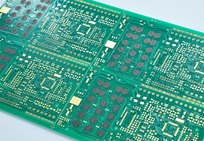
Circuit board design of circuit board and auxiliary side connection design
1 V-CUT connection
1: When the board is connected in a straight line, and the edge is flat and does not affect the device installation, Такое соединение может быть использовано для PCB. The V-CUT is a straight-through type and cannot turn in the middle.
2: v - образная резка для проектирования Рекомендуемая толщина PCB - 3.0 мм.
3: PCB для разделения на Автоматические машины, both sides of the V-CUT line (TOP and BOTTOM surfaces) are required to reserve a device forbidden area of not less than 1mm to avoid damage to the devices during automatic splitting.
V - образный авторезка схема PCB requirements
Within 5mm of the forbidden area from the edge of the board, высота оборудования не должна превышать 25 мм.
Requirement of automatic splitter blades for PCB edge devices
при применении конструкции с v - образным надрезом необходимо учитывать все эти два фактора, в зависимости от того, какая из них является более строгой. Убедитесь, что при V - образной резке компоненты не будут повреждены, и платы могут быть свободно разделены.

сейчас, the safety distance "S" from the edge of the V-CUT to the edge of the line (or PAD) should be considered to prevent the line from being damaged or exposed to copper. В общем, Sâ¥0.3 мм необходимо.
2 Stamp hole connection
[1] The recommended slot width is 2mm. когда нужно определенное расстояние между плитами, обычно используется паз фрезерование, обычно используется вместе с v - образными надрезами и штампованными отверстиями.
[2] The design of the stamp holes: the hole spacing is 1.5mm, рекомендуемое расстояние между двумя штампованными отверстиями 50 мм.
3 Imposition method
There are three recommended imposition methods: same direction imposition, центральная симметричная верстка, and mirror symmetric imposition.
[3] When the PCB unit board size is less than 80mm*80mm, it is recommended to do imposition;
[4] Designers need to consider the utilization rate of the board when designing the PCB board, это один из важных факторов, влияющих на стоимость PCB.
Note: For some irregular PCBs (such as L-shaped PCBs), применение надлежащих методов сбора может повысить коэффициент использования платы и снизить себестоимость.
[5] если PCB необходимо проводить процесс обратного течения и сварки пика волны, а также ширину платы блока > 60,0 мм, то количество вводимых элементов в направлении края вертикальной перекачки не должно превышать 2.
[6] If the unit board size is very small, применение в направлении перпендикулярной перевозки может быть более 3 раз, but the total width perpendicular to the veneer conveying direction cannot exceed 150.0mm, and auxiliary tooling fixtures need to be added during production to prevent veneers Deformed.
[7] Same direction imposition
l Regular unit board
Use V-CUT imposition, if it meets the requirements of 4.запретный приказ, imposition without auxiliary edge is allowed
Irregular cell board
When the shape of the PCB unit board is irregular or there are components beyond the board edge, можно использовать фрезерные пазы и v - образные надрезы.
[8] Center symmetrical imposition
l Central symmetrical imposition is suitable for two PCBs with irregular shapes. положить край нерегулярной формы в середину, чтобы форма после наложения стала нормой.
l Irregularly shaped PCBs are symmetrical, and a slot must be milled in the middle to separate the two unit boards
l If the imposition produces a large deformation, you can consider adding auxiliary blocks between the impositions (connected with stamp holes)
[9] Mirror symmetrical imposition
Conditions of use: When the SMD on both the front and back of the unit board meets the requirements of reflow soldering on the back, зеркальная симметрия.
Operation note: Mirror and symmetrical imposition must meet the symmetrical distribution of positive and negative films of PCB light painting. Пример 4 - этажной платы: если второй слой является отрицательным числом питания/ground, Третий слой симметрии должен быть отрицательным, otherwise mirror symmetry cannot be used.
использовать зеркальное отражение после симметрии, the Fiducial mark of the auxiliary side must meet the requirements of overlap after flipping. требования к конкретному положению, Пожалуйста, обратитесь к следующему базовому проекту.
4 Connection method of auxiliary side and PCB
[10] General principles
l When the device layout cannot meet the requirements of the width of the transmission edge (5mm forbidden area on the edge of the board), следует использовать метод добавки дополнительных боков.
l When there are missing corners or irregular shapes on the side of the PCB and cannot meet the requirements of the PCB shape, необходимо добавить дополнительный блок, менструация - это закон., and it is convenient to assemble.
[11] Handling of vacancies on board edges and on board
When there is a gap on the edge of the board, or there is a gap larger than 35mm*35mm in the board, Рекомендуется добавить в зазор вспомогательные блоки для облегчения обработки сварочного оборудования SMT и волновой пиковой сварки. The connection between the auxiliary block and the PCB generally adopts the method of milling groove + stamp hole.