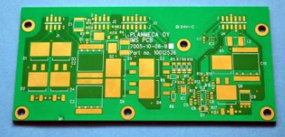
внимание на сопротивление печатных плат
Хорошая слоистая структура может эффективно управлять сопротивлением, его проводка может формировать структуру линии передачи, которая легко поддается пониманию и прогнозированию. Эти проблемы могут быть успешно решены с помощью средств решения на местах, которые позволяют получить достаточно точные результаты, если число переменных будет минимальным.

Однако, при сложении трех или более сигналов, this is not necessarily the case, причина деликатна. The target impedance value depends on the process technology of the device. высокая скорость CMOS технологии, как правило, может быть около 70 байт; высокоскоростное TTL оборудование обычно может достигать 80 © до 100 © или около. Because the impedance value usually has a great influence on noise tolerance and signal switching, при выборе импеданса необходимо быть очень осторожным; Руководство по продукции.
The initial results of the on-site resolution tool may encounter two kinds of problems. прежде всего, проблемы с ограниченным кругозором. The field solution tool only analyzes the influence of nearby traces, параллельные дорожки на других слоях без учёта влияния импеданса. The on-site solution tool cannot know the details before wiring, То есть, when assigning the trace width, Вместе с тем, вышеупомянутый метод паренной расстановки может свести к минимуму эту проблему.
It is worth mentioning the influence of partial power planes. The outer circuit board is often crowded with grounded copper wires after wiring, which is beneficial to suppress EMI and balance plating. Было бы хорошо, если бы космическое пространство приняло такие меры., the laminated structure recommended in this article will have a very small effect on the characteristic impedance.
эффект использования большого количества соседних слоёв сигнала очень заметен. Some on-site solution tools cannot find the presence of copper foil, Потому что она может проверять только полосы печати и весь слой, so the impedance analysis result is incorrect. когда металл на соседнем слое, it acts like a less reliable ground layer. если сопротивление слишком низкое, the instantaneous current will be large, Это практическая и чувствительная проблема EMI.
Another reason for the failure of impedance analysis tools is distributed capacitors. These analysis tools generally cannot reflect the influence of pins and vias (this influence is usually analyzed with a simulator). это влияние может быть очень значительным, especially on the backplane. The reason is very simple:
The characteristic impedance of PCB proofing can usually be calculated by the following formula: âL/C
Among them, L and C are the inductance and capacitance per unit length respectively.
Если штифт равномерный, the additional capacitance will greatly affect the calculation result. The formula will become:
âL/(C+C')
C'is the pin capacitance per unit length.
Если соединение соединяется по прямой, the total line capacitance and the total pin capacitance except the first and last pins can be used. такой, the effective impedance will be reduced, Возможно даже с 80 до 8. In order to obtain the effective value, the original impedance value needs to be divided by:
â(1+C'/C)
This calculation is very important for component selection.
имитация запаздывания, the capacitance of the component and the package (and sometimes the inductance should also be included) should be considered. надо обратить внимание на два вопроса. First, Симулятор может быть не в состоянии правильно имитировать распределённые конденсаторы; Следующий, pay attention to the impact of different production conditions on incomplete layers and non-parallel traces. Многие инструменты полевых решений не могут анализировать распределение стека без полного питания или залегания. However, if there is a ground layer adjacent to the signal layer, задержка планирования будет довольно плохой, such as a capacitor, максимальная задержка; Если двухсторонняя пластинка на обоих слоях имеет много заземления и фольги VCC, This situation is even more serious. Если этот процесс не автоматизирован, setting up these things in a CAD system will be very messy.
PCB proofing EMC
There are many factors affecting EMC, many of which are usually not analyzed. Даже если их проанализировали, it is often after the design is completed, очень поздно. The following are some factors that affect EMC:
The slots in the power plane constitute a quarter-wavelength antenna. случай, когда на металлический контейнер необходимо установить пазы, drilling methods should be used instead.
индуктивный элемент. I once met a designer who followed all the design rules and made simulations, но на его платы все еще много излучающих сигналов. The reason is that there are two inductors placed parallel to each other on the top layer to form a transformer.
из - за влияния неполной плоскости, the low impedance of the inner layer causes a large transient current in the outer layer.
Большинство из этих вопросов можно было бы избежать с помощью оборонительного проектирования. First of all, Необходимо разработать правильную политику стека и проводки, это хорошее начало.
The above is the introduction to the characteristic impedance of PCB proofing. Ipcb также предоставляет Производители PCB and PCB manufacturing technology