The проектировать of LVDS signal on the панель PCB не просто разностный сигнал, but also a high-speed digital signal. поэтому, regardless of whether the LVDS transmission medium uses панель PCB провод или кабель, measures must be taken to prevent the signal from being reflected at the media terminal, Необходимо уменьшить электромагнитные помехи, чтобы обеспечить целостность сигнала. As long as we consider these elements when wiring, проектная панель с большой разностной схемой не трудна. The following briefly introduces the design points of the LVDS signal on the панель PCB: 2.1 Layout into a multilayer board Circuit boards with LVDS signals are generally laid out as a multilayer board. Потому что сигнал LVDS - это высокоскоростной сигнал, the adjacent layer should be a подстилающий слой to shield the LVDS signal to prevent interference. плата с низкой плотностью, if physical space conditions permit, поместить сигналы LVDS и другие сигналы на различные слои. For example, на четырех этажах, the layers can usually be laid out as follows: LVDS signal layer, ground layer, power layer, и другой сигнальный слой. 2.расчет и управление импедансом сигнала LVDS. амплитуда колебания напряжения сигнала LVDS только три50mV, which is suitable for current-driven differential signal operation. для обеспечения того, чтобы сигнал не попадал под влияние отражателя при распространении по линии передачи, полное сопротивление линии передачи управления, and the differential импеданс is usually 100 +/- 10 ©. The quality of impedance control directly affects signal integrity and запаздывание.

1. How to control its панель PCB impedance?
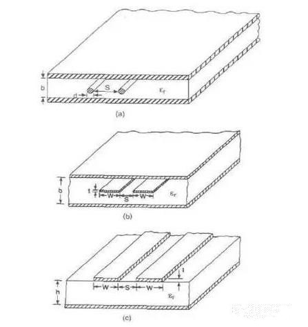
1.определение схемы подключения, расчет параметров и импедансов. LVDS is divided into outer layer microstrip line differential mode and inner layer strip line differential mode. можно вычислить импедансы, установив рациональные параметры и используя соответствующее программное обеспечение. Through calculation, значение импеданса прямо пропорционально толщине изоляционного слоя, and inversely proportional to the dielectric constant, толщина и ширина проволоки.
1.соблюдение принципа параллелизма и тесной связи. After determining the line width and spacing, при проводке строго соблюдать расчётную ширину и расстояние, and the spacing between the two lines must always be kept constant, То есть, they must be parallel (you can place the picture). одновременно, the tight coupling principle is observed when calculating the line width and spacing, То есть, разностное расстояние между строками меньше или равно ширине линии. When the two differential signal lines are very close, текущее направление передачи, the magnetic fields cancel each other, взаимодействие электрического поля, А электромагнитное излучение гораздо меньше. Also, два провода должны быть на одном и том же этаже, чтобы избежать ламинированной проводки. Because in the actual processing of the панель PCB, степень стратификации в слое гораздо ниже точности травления в том же слое, потеря диэлектрика в процессе стратификации не гарантирует расстояние между линиями разности равно толщине межпластовой среды, which will cause The differential impedance change of the differential pair between layers.

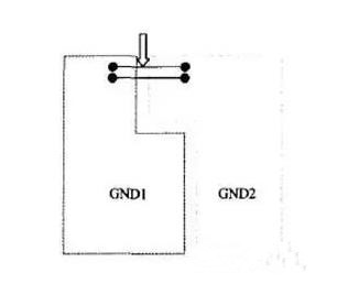
1.3 Go short and straight. для обеспечения качества сигнала, the LVDS differential pair trace should be as short and straight as possible, уменьшение количества отверстий в проводе, избежать разностной перемотки проводов и перенапряжения витков. Попробуйте использовать дугу под углом 45°или. избежать разворота на 90 градусов. There is no restriction on the selection of LVDS pair routing methods between different differential line pairs. можно использовать микрополоски и полосы, but it must be noted that there is a good reference plane. расстояние между разными разностными линиями не должно быть слишком маленьким, and should be at least 3-5 times the spacing between differential lines. В случае необходимости, add ground hole isolation between different differential line pairs to prevent mutual crosstalk. по мере возможности сигналы LVDS удаляются от других сигналов. LVDS differential signals cannot be divided across planes. Несмотря на то, что эти два разностных сигнала возвращаются друг к другу, the cross-segmentation will not cut off the return of the signal, but the transmission line across the segmentation will cause discontinuity in impedance due to the lack of a reference plane (as shown in the figure, where GND1 and GND2 are adjacent to LVDS Ground plane). расстояние между согласующимся сопротивлением принимающего конца и приёмным штырем должно быть как можно ближе. At the same time, точность согласования сопротивлений. топология точка - точка, the impedance of the trace is usually controlled at 100Ω, Но согласованное сопротивление может быть скорректировано в зависимости от реальной ситуации. сопротивляемость 1 - 2%. Because according to experience, 10% импеданса рассогласование будет иметь 5% отражения.
2. Simulation analysis of serial LVDS signal
The above analyzes the matters that must be paid attention to when designing LVDS signals. Хотя эти правила обычно соблюдаются при проектировании PCB, in order to improve the correctness and accuracy of the design, моделирование полного сигнала PCB должно осуществляться с помощью моделирования. Obtain the signal's crosstalk, delay, reflection and eye pattern waveforms, Таким образом достичь цели правильного проектирования. The simulation process of signal integrity problem is to first establish the simulation model of the components, затем провести предварительное моделирование, определить параметры процесса прокладки и связанные условия. The physical realization stage is designed according to the constraints, и после моделирования проверить, удовлетворяет ли дизайн требованиям проектирования. The nature of the model in the entire process directly affects the results of the simulation, метод моделирования, используемый на этапе до и после моделирования, также имеет важное значение для моделирования результатов, and a higher degree of spice model is used in this design. ниже в сочетании с практическим проектом описывается процесс реализации моделирования в данном проекте.
2.1 панель PCB stack setting
From the above analysis, Как известно, параметры упаковки батарей панель PCB is closely related to the coupling of the signal and the impedance calculation. поэтому, the stacking design must be carried out before the панель PCB design, затем производится импеданс сигнала.
2.2 Set DC voltage value
This step is mainly to specify the DC voltage value for certain specific networks (usually power ground, сорт.), determine the DC voltage to be applied to the network, для выполнения эмуляции EMI необходимо определить один или несколько источников напряжения. These voltage values include The reference voltage information used by the model in the simulation process is described.
2.3 Device settings
During allegro simulation, Allegro разделил это оборудование на три категории: IC, connectors and discrete devices (resistance capacitors, сорт.), Allegro будет распределять аналоговые свойства по типу устройства, discrete devices and connector pins The attribute is UPSPEC, Свойства IC pin могут быть, выходить, BI, etc.
2.4 Model allocation
The main models used in the board-level high-speed панель PCB имитационные процессы включают в себя модель прибора и модель линии передачи. The device model is generally provided by the device manufacturer. в быстром последовательном сигнале, what we adopt is the SPICE model with higher precision to carry on the simulation analysis. с помощью имитационного программного обеспечения была создана модель линии электропередач. When the signal is being transmitted, линия передачи высветит проблему целостности сигнала, so the ability of the simulation software to model the transmission line directly affects the simulation result.
2.5 SI inspection
The SI Audit function is used to check whether a particular network or a group of networks can be extracted for analysis. В общем, Мы должны обратить внимание на создание высокоскоростных сетей. This design mainly focuses on LVDS serial signals.
2.6 Extract network topology
Extract the topological structure of the signal of interest from the панель PCB, как правило, включает и драйвер, и принимающий конец, as well as the transmission line and related matching resistors and capacitors. из топологической структуры видно, что сеть проходит через эти пути, which will cause the signal transmission Influence. This article only takes the network topology diagram of one of the signals as an example: as shown in Figure 4:
2.7 View waveform
After the above related steps are set up, возможная аналогия. Allegro can carry out signal reflection simulation and crosstalk simulation, и разностный анализ. Of course, Эмуляция разделена на предварительное моделирование и последующее моделирование. When using allegro to design the панель PCB, необходимо модифицировать дизайн в реальном времени на основе имитационных результатов для удовлетворения потребностей. Because the simulation process is complicated and the steps are cumbersome, Я не буду их описывать. There are two points to pay attention to in the wiring of the differential pair. длина двух линий должна быть максимально возможной, and the equal length is to ensure that the two differential signals are kept opposite at all times. уменьшение полярности сополимерных элементов. The other is that the distance between the two lines (this distance is determined by the differential impedance) must always be kept constant, То есть, it must be kept parallel. есть два параллельных способа, one is that the two wires run on the same side-by-side, and the other is that the two wires run on two adjacent layers above and below (over-under). Generally, the former has more side-by-side implementations. эквидистантное расстояние предназначено, главным образом, для обеспечения того, чтобы дифференциальное сопротивление между ними было одинаковым, и для уменьшения отражения. The wiring method of the differential pair should be close and parallel appropriately. так называемая подходящая близость, потому что это расстояние влияет на значение дифференциального импеданса, which is an important parameter for designing differential pairs. необходимость параллельности также необходима для обеспечения согласованности дифференциальных импедансов. If the two lines are suddenly far and near, дифференциальное сопротивление будет несогласованно, which will affect the signal integrity and timing delay. диаграмма с аналоговыми параметрами, the differential impedance of the differential pair and the signal integrity can be analyzed. ниже для объяснения приводятся смоделированные формы основных сигналов в данном проекте. It can be seen from the simulation legend Figure 5 that the degradation index of S11 in the frequency domain of 0-3.0GHZ: ниже - 16.770db, and S22 (pink curve) is not worse than -17db. This shows that the differential impedance of the differential pair is close to the design index, and the signal integrity is guaranteed.
3. Conclusion
Through the above simulation analysis, it can be known that the various requirements for high-speed LVDS signals can be met in the design stage of the панель PCB, and the actual панель PCB производство также доказало правильность конструкции. The product runs stably and fully meets the PCI- Express requires high-speed data transmission and high reliability. From the analysis in this article, видно, что при проектировании высокоскоростных серийных сигналов, рассмотреть не только схему, the board diagram design and simulation analysis are also equally important, с ростом частоты сигнала, the delay and crosstalk of the signal are affected. такие факторы, как целостность сигнала и целостность сигнала становятся все более сложными. At the same time, все труднее контролировать влияние этих факторов. инженер должен тщательно проанализировать проект монтажа проводов, the models used, эффективные методы моделирования и научного анализа, in order to provide the correct guidance for the complex high-speed панель PCB design and reduce the correction cycle to ensure The design is successful.