Three important measures to improve the thermal reliability of printed boards
Provide fast, профессионально - техническое развитие, product development and auxiliary development technical services for various electronic enterprises, научно - исследовательский институт. Zhilian Technology continues to develop and innovate. основы теплового проектирования, the selection of heat dissipation methods, техническое мероприятие по проектированию и термоанализу зданий проектирование PCBare discussed. внедрение теплоанализа и теплового проектирования в качестве трех важных мер повышения теплонадежности печатных плат.
1. The importance of thermal design
In addition to useful work, большая часть электрической энергии, расходуемой электронным оборудованием в процессе эксплуатации, преобразуется в тепло и диссипируется. The heat generated by the electronic equipment causes the internal temperature to rise rapidly. Если тепло не растает вовремя, the equipment will continue to heat up, оборудование устаревает из - за перегрева, and the reliability of the electronic equipment will decrease.
SMT повышает плотность установки электронного оборудования, reduces the effective heat dissipation area, А повышение температуры оборудования серьезно влияет на его надежность. Therefore, очень важное значение имеют исследования термического проектирования.
2. Analysis of temperature rise factors of printed circuit boards

The direct cause of the temperature rise of the printed board is due to the existence of power consumption devices in the circuit, мощность электронного оборудования различной степени, интенсивность нагрева изменяется в зависимости от размера потребляемой энергии.
Two phenomena of temperature rise in printed boards:
(1) Local temperature rise or large area temperature rise;
(2) Short-term temperature rise or long-term temperature rise.
тепловой расход при анализе PCB, it is generally analyzed from the following aspects.
2.1 Electrical power consumption
(1) Analyze the power consumption per unit area;
(2) Analyze the distribution of power consumption on the PCB.
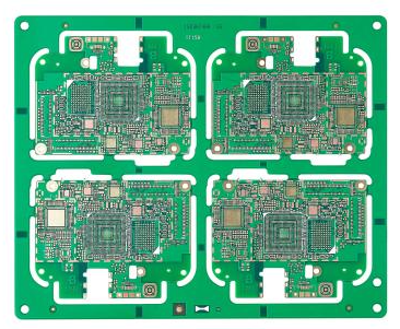
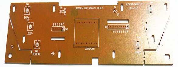
2.2 The structure of the printed board
(1) The size of the printed board;
(2) The material of the printed board.
2.3 The installation method of the printed board
(1) Installation method (such as vertical installation, horizontal installation);
(2) The sealing condition and the distance from the case.
2.4 Thermal radiation
(1) The emissivity of the printed board surface;
(2) The temperature difference between the printed board and adjacent surfaces and their absolute temperature;
2.5 Heat conduction
(1) Install the radiator;
(2) Conduction of other installation structural parts.
2.6 Thermal convection
(1) Natural convection;
(2) Forced cooling convection.
The analysis of the above factors from the PCB is an effective way to solve the temperature rise of the printed board. в продуктах и системах эти факторы часто взаимосвязаны и зависят друг от друга. Most of the factors should be analyzed according to the actual situation, более точный расчет или оценка таких параметров, как повышение температуры и потребление энергии.
3. Thermal design principles
3.1 Material selection
(1) The temperature rise of the conductors of the printed board due to the passing current plus the specified ambient temperature should not exceed 125 â (commonly used typical value. It may be different depending on the selected board). Since the components installed on the printed board also emit some heat, это влияет на рабочую температуру, these factors should be considered when selecting materials and the design of the printed board. температура в горячей точке не должна превышать 125 × 13132г.. Choose thicker copper clad as much as possible.
(2) In special cases, aluminum-based, хрупкий на керамической основе, and other plates with low thermal resistance can be selected.
(3) Adopting multi-layer board structure helps PCB thermal design.
3.2 Ensure that the heat dissipation channel is unblocked
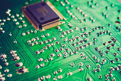
(1) Make full use of the components layout, copper skin, открыть окно и отверстие для отвода тепла создать разумный и эффективный канал для снижения теплового сопротивления, чтобы обеспечить плавный вывод тепла в помещениеPCB.
(2) Setting of heat dissipation through holes
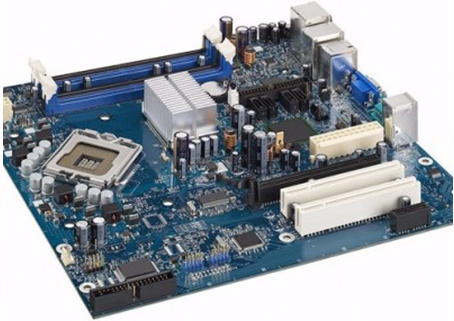
Designing some heat dissipation through holes and blind holes can effectively increase the heat dissipation area and reduce the thermal resistance, and improve the power density of the circuit board. например, a via hole is set up on the pad of the LCCC device. в процессе производства схемы заполнения припоя, чтобы увеличить теплопроводность. The heat generated during circuit operation can be quickly transferred to the metal heat dissipation layer or the copper pad on the back through the through holes or blind holes to be dissipated. в определенных случаях, a circuit board with a heat dissipation layer is specially designed and used. тепловыделяющий материал обычно является медью./molybdenum and other materials, например, некоторые модули питания.
(3) Use of thermally conductive materials
In order to reduce the thermal resistance of the heat conduction process, использование теплопроводных материалов для повышения теплопроводности на соприкосновении между приборами с высоким энергопотреблением и основной пластиной.