Процесс проектирования от схем до PCB
Установите параметры элемента - > Принцип ввода Сетевая таблица - > Параметры проектирования - > Ручная компоновка - > Ручная проводка - > Проверка дизайна - > Обзор - > Выход кулачка.
Параметры: Расстояние между соседними проводами должно соответствовать требованиям электрической безопасности, и расстояние должно быть как можно шире, чтобы облегчить работу и производство. Минимальное расстояние должно быть, по крайней мере, подходящим для переноса напряжения. При низкой плотности проводки расстояние между линиями сигнала может быть соответствующим образом увеличено для удовлетворения высокого напряжения. Сигнальные линии с большой разностью низкого уровня должны быть как можно короче и увеличены. Расстояние между проводами обычно составляет 8 миль. Расстояние между краем отверстия в сварном диске и краем печатной пластины должно быть больше 1 мм, что позволяет избежать дефектов в сварном диске в процессе обработки. Когда проводка, соединенная с сварным диском, тонкая, соединение между сварным диском и проводом должно быть сконструировано как капля воды. Это имеет преимущество, что сварочный диск нелегко отсоединить, но проводка и сварочный диск нелегко отключить.
3.Практика компоновки компонентов доказывает, что даже если принципиальная схема схемы спроектирована правильно, неправильная конструкция печатной платы может негативно повлиять на надежность электронного оборудования. Например, если две тонкие параллельные линии печатной платы находятся рядом друг с другом, образуется задержка формы сигнала и образуется отраженный шум на зажимах линии передачи;
4. Из - за источника питания
помехи, вызванные плохим учетом земной линии, снижают производительность продукта. Поэтому при проектировании печатных плат мы должны обратить внимание на правильный подход.

Каждый переключатель имеет четыре электрических цепи:
1. коаксиальный ультра - высокой частоты УВЧ типа бабочка переменного тока выключателя питания
2. коаксиальный ультра - высокой частоты УВЧ типа бабочка переменного тока выходного выпрямителя
3. контур тока источника входного сигнала
4. коаксиальный ультра - высокой частоты УВЧ типа бабочка тока выходной нагрузки
Входная схема заряжает входной конденсатор приближенным током постоянного тока, а фильтрующий конденсатор в основном выполняет роль широкополосного накопления энергии; Аналогичным образом, конденсаторы выходного фильтра также используются для хранения высокочастотной энергии от выходного выпрямителя и устранения энергии постоянного тока от схемы выходной нагрузки. Поэтому очень важны входные и выходные фильтры конденсаторов.
Схемы входного и выходного токов должны быть подключены к источнику питания отдельно от зажимов фильтрующего конденсатора; Если соединение между входной / выходной цепью и цепью переключателя / выпрямителя питания не может быть напрямую связано с зажимом конденсатора, энергия переменного тока будет излучаться в окружающую среду через входной или выходной фильтр конденсатора.
Схема переменного тока переключателя питания и цепь переменного тока выпрямителя содержат высокоамплитудный трапециевидный ток. гармоническая составляющая этих токов очень высока, и их частота намного выше базовой частоты переключателя. Пиковые амплитуды могут достигать 5 раз амплитуды непрерывного входного / выходного тока постоянного тока, и время перехода обычно составляет около 50 ns.
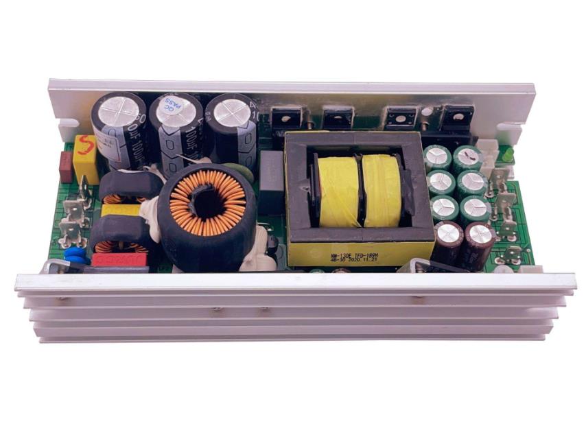
Эти две схемы наиболее уязвимы для электромагнитных помех, поэтому эти схемы переменного тока должны быть проложены перед другими печатными проводами в источнике питания. Три основных компонента каждой схемы фильтр конденсатор выключатель питания или выпрямитель индуктор или трансформатор должны быть расположены рядом друг с другом и регулировать положение элемента, чтобы путь тока между ними был как можно короче.
Оптимальный способ создания схемы питания переключателя аналогичен его электрическому дизайну. Оптимальный процесс проектирования выглядит следующим образом:
:: Установка трансформаторов
:: Конструкция токовых цепей для выключателей питания
* Проектирование электрического контура выходного выпрямителя
* Подключение цепи управления к цепи питания переменного тока
:: Проектирование схемы источника входного тока и входного фильтра
При проектировании схемы выходной нагрузки и выходного фильтра, в зависимости от функциональной ячейки схемы, компоновка всех компонентов схемы должна соответствовать следующим принципам:
1) Сначала рассмотрим размеры PCB. Когда размер платы PCB слишком большой, длинная печатная линия, увеличение сопротивления, снижение шумостойкости, стоимость также увеличивается; Если он слишком мал и плохо рассеивает тепло, соседние линии могут быть легко нарушены. Оптимальной формой платы является прямоугольник с соотношением сторон 3: 2 или 4: 3. Компоненты, расположенные на краю платы, как правило, находятся на расстоянии не менее 2 мм от края платы.
2) При размещении оборудования, подумайте о будущей сварке, не слишком плотно
3) Сосредоточьтесь на основных компонентах каждой функциональной схемы и размещайте их вокруг. Компоненты должны быть равномерно и аккуратно размещены. Они должны быть компактно размещены на платах PCB, чтобы минимизировать и сократить провода и соединения между компонентами, а емкость развязки должна быть как можно ближе к VCC компонентов
4) Для схем, работающих на высоких частотах, следует учитывать параметры распределения между элементами. Для общих схем детали должны быть расположены как можно параллельно. Таким образом, он не только эстетичен, но и легко собран и сварен, его легко производить серийно.
5) Расположение каждого функционального элемента схемы в соответствии с процессом цепи, чтобы компоновка облегчала поток сигнала и, насколько это возможно, удерживала сигнал в одном направлении.
6) Первый принцип компоновки заключается в том, чтобы обеспечить скорость прокладки проводов. При перемещении устройства обращайте внимание на соединение летающих линий и объединяйте связанные устройства.
7) Сведение к минимуму площади контура и подавление радиационных помех от источника питания переключателя

Электрический переключатель содержит высокочастотные сигналы.
Любая печатная линия на PCB может служить антенной.
Длина и ширина печатной линии влияют на ее сопротивление и реактивность, что влияет на частотную реакцию. Даже печатные линии, проходящие через DC - сигналы, могут связываться с RF - сигналами от соседних печатных линий и вызывать проблемы с цепью (и даже повторно излучать сигналы помех). Поэтому все печатные линии, проходящие через ток переменного тока, должны быть спроектированы как можно короче и шире, а это означает, что все компоненты, подключенные к печатным линиям и другим линиям электропередач, должны быть близки друг к другу. Длина печатной линии пропорциональна ее индуктивности и сопротивлению, а ширина обратно пропорциональна ее индуктивности и сопротивлению. Эта длина отражает длину волны отклика печатной линии. Чем длиннее, тем ниже частота передачи и приема электромагнитных волн печатной линией, тем больше радиочастотной энергии может излучаться. В зависимости от тока печатной платы, максимизируйте ширину линии электропитания и уменьшайте сопротивление контура. В то же время направление выключения линии электропитания совпадает с направлением тока, что помогает повысить устойчивость к шуму. Заземление - это нижняя ветвь четырех электрических контуров переключателя питания. В качестве общей точки отсчета схемы он играет очень важную роль. Это важный способ контроля помех. Поэтому при компоновке следует тщательно продумать размещение заземленных линий. Смешивание различных заземленных линий может привести к нестабильности питания.
При проектировании необходимо обратить внимание на следующие моменты.
1. Правильный выбор одноточечного заземления. Как правило, общий конец фильтрующего конденсатора должен быть единственной точкой соединения между другим местом заземления и местом большого тока. Место заземления цепи того же уровня должно быть как можно ближе, а к месту заземления этой ступени должен быть подключен фильтрующий конденсатор мощности цепи уровня тока, главным образом с учетом того, что ток, возвращающийся к земле различными частями цепи, изменяется, поскольку сопротивление линии фактического потока приводит к изменению потенциала земли в каждой части цепи и введению помех. В этом переключательном источнике питания индуктивное влияние между его проводом и устройством невелико, а циклический ток, образованный цепью заземления, оказывает большое влияние на помехи, поэтому используется небольшое заземление, цепь тока переключателя питания (заземление нескольких устройств в цепи питания подключено к заземлению, а несколько устройств в цепи выходного выпрямительного тока подключены к заземлению соответствующего фильтрующего конденсатора, так что питание работает более стабильно и нелегко самовозбуждаться. Когда одноточечное заземление не может быть достигнуто, два диода или одно небольшое сопротивление соединяются в общем заземлении и могут быть соединены с относительно медной фольгой в куске.
2. Как можно больше заземления. Если заземление тонкое, потенциал заземления изменяется с изменением тока, что приводит к нестабильному уровню сигнала времени и снижению шумостойкости электронных устройств. Поэтому необходимо обеспечить, чтобы заземляющие зажимы каждого большого тока имели как можно более короткий и широкий печатный провод и максимально широкий источник питания. Их отношения: заземление > линия электропитания > линия сигнала. По возможности, ширина заземления должна быть больше 3 мм. Большая площадь медного слоя также может использоваться в качестве заземления. Все неиспользуемые места на печатной доске соединены с землей как заземление.
При проведении глобальной проводки необходимо соблюдать следующие принципы.
1. Направление соединения: с точки зрения сварной поверхности расположение элементов должно быть как можно более согласовано с принципиальным планом, а направление соединения должно соответствовать направлению соединения схемы. Поскольку производственный процесс обычно требует тестирования различных параметров на сварной поверхности, это облегчает проверку при производстве, отладке и обслуживании (примечание: при условии соблюдения требований к характеристикам схемы, монтажу всей машины и расположению панели).
2. При проектировании схемы проводки должны быть как можно меньше витков, ширина линии на дуге печати не должна быть внезапной, угол линии должен быть 90 градусов, чтобы сделать линию простой и ясной.
3. В печатных схемах не допускаются перекрестные схемы. Для проводов, которые могут пересекаться, используются два решения: "бурение" и "намотка". То есть, пусть провод переходит от другого сопротивления к конденсатору. Разрыв в нижней части триода « пробурен» или « намотан» с одного конца потенциально пересекающегося провода. В особых случаях схема очень сложная. Чтобы упростить конструкцию, также разрешается соединять кабельные мосты для решения проблемы перекрестных цепей. Из - за использования одной панели, прямые элементы расположены в верхней части, устройство для установки поверхности находится в нижней части, поэтому при компоновке прямолинейные компоненты могут перекрываться с устройством для установки поверхности, но следует избегать перекрытия сварного диска.
4. Источником питания входного и выходного переключателей заземления является DC - DC низкого давления. Для обратной связи выходного напряжения в начале трансформатора схемы с обеих сторон должны иметь заземление с общей ссылкой. Поэтому, после прокладки меди на заземленных линиях с обеих сторон, они должны быть соединены, чтобы сформировать общее заземление
Проверка PCB
После завершения компоновки PCB проводки необходимо тщательно проверить, соответствует ли конструкция проводки правилам, установленным дизайнером, и подтвердить, соответствуют ли установленные правила требованиям процесса производства печатных листов. Как правило, проверяется, является ли расстояние между проводами и проводами и сварными дисками элементов, а также между сварными дисками с сквозными отверстиями и сквозными отверстиями разумным и соответствует ли оно производственным требованиям.
Соответствует ли ширина линии электропитания и заземления и есть ли место на монтажной плате, где можно расширить линию. Примечание: Некоторые ошибки можно игнорировать. Например, часть контура некоторых разъемов помещается вне рамок панели, и при проверке расстояния между ними возникают ошибки; Кроме того, каждый раз, когда вносятся изменения в проводку и пробоины, медное покрытие должно быть выполнено снова.
В соответствии с « Таблицей проверки PCB», в том числе правила проектирования и слои определяют ширину линии прокладки для установки перфорации, мы также должны сосредоточиться на проверке макета оборудования и питания рациональной наземной сети проводки, проводки и защиты высокоскоростной сети часов, размещения и соединения развязных конденсаторов и так далее.
Обратите внимание на дизайн и вывод фотографических файлов:
1. Выходной слой - это проводной (нижний) слой шелковой печати (включая верхнюю шелковую печать и нижнюю шелковую печать), блокирующий сварку (нижний слой)
2. При установке слоя слоя шелковой сетки не выбирайте тип детали, выбирайте текст контура верхнего (нижнего) слоя и слоя шелковой сетки. Линек. При настройке каждого слоя выберите контур панели. При настройке слоя шелковой сетки выбирайте не тип детали, а контур верхнего (нижнего) слоя и слоя шелковой сетки Text. Линия d. При создании файла скважины используйте настройки по умолчанию для панели Powerpcb без каких - либо изменений.