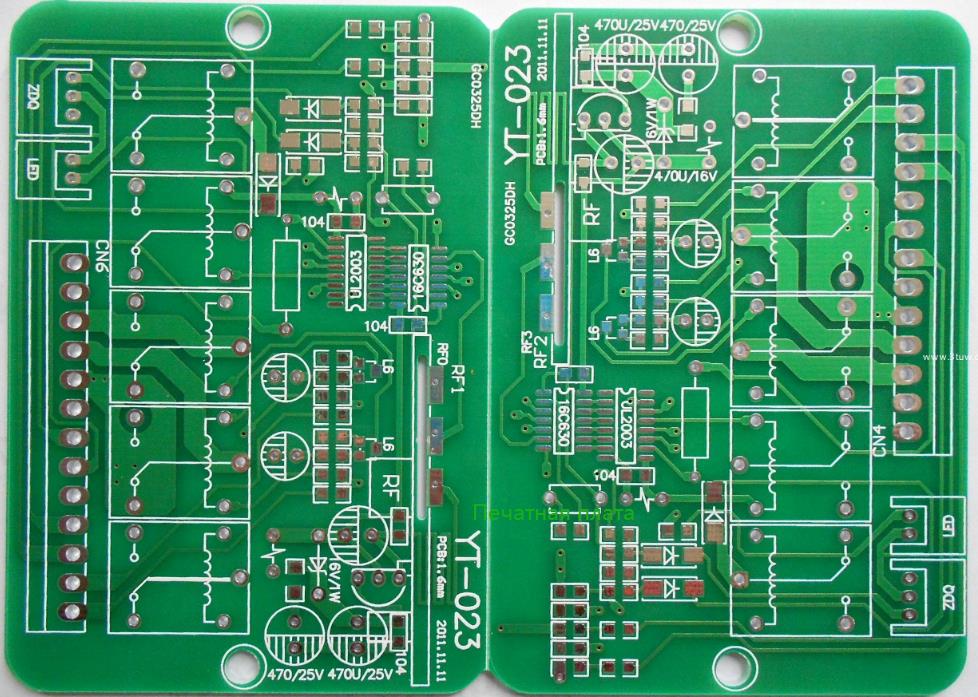
PCB (Printed Circuit Board), китайское название печатная плата, также известная как печатная плата, является важным электронным компонентом и опорой электронных компонентов.Поскольку он был изготовлен с использованием электронной печати, он был назван "печатной" платы.
Процесс производства pcb
Производство печатные платы очень сложное, возьмите четырехслойную печатную пластину в качестве примера, процесс производства в основном включает в себя компоновку PCB,изготовление стержневой пластины, перенос внутренней компоновки схема платы,перфорацию и проверку стержневой пластины,ламинирование,бурение,химическое осаждение меди на стенке отверстия, перенос наружной компоновки PCB,травление наружного PCB и другие шаги.
1.Формирование pcb
Первым шагом в создании печатные платы является сортировка и проверка компоновки PCB Layout.Производственные заводы Печатная плата получают CAD - файлы от Компания PCB Design и поскольку каждое программное обеспечение CAD имеет свой собственный уникальный формат файлов, завод схема платы преобразуется в единый формат Extended Gerber RS 274X или Gerber X2.Затем инженеры завода проверяют компоновку Печатная плата на соответствие процессу производства,есть ли какие либо дефекты и так далее.
2.Изготовление пластины
Очистка медной пластины, если есть пыль, может привести к короткому замыканию или отключению последней цепи.
3.Перенос внутренней конфигурации схема платы
Сначала нужно сделать двухуровневую линию из самой промежуточной пластины (Core). После очистки медная пластина покрывает поверхность светочувствительной пленкой. Эта пленка затвердевает при контакте со светом,образуя защитную пленку на медной фольге из полимерной медной пластины. Двухэтажная плёнка PCB и двухслойная медная пластина, наконец, вставляются в верхний слой плёнки Печатная плата,чтобы обеспечить точное положение слоя плёнки схема платы в верхнем и нижнем слоях. Сенсорная машина использует УФ - лампу для облучения светочувствительной пленки на медной фольге, светочувствительная пленка отверждается под прозрачной пленкой, непроницаемой пленкой или без отвержденной светочувствительной пленки. Медная фольга, покрытая под отвержденной светочувствительной пленкой, является необходимой линией компоновки PCB, что эквивалентно роли чернил лазерного принтера ручной работы PCB. Затем неотвратимая светочувствительная пленка очищается щелочью,а требуемая медная фольга покрывается отвержденной светочувствительной пленкой.Затем используйте сильную щелочь, такую как NaOH, чтобы травить ненужную медную фольгу.Оторвите отвержденную светочувствительную пленку,чтобы показать медную фольгу,необходимую для схемы PCB.

4. Прорыв и проверка стержня
Цилиндр был успешно изготовлен. Затем на стержневой пластине выровняют отверстия, чтобы облегчить последующее выравнивание с другими материалами. После того, как стержневая пластина вместе с другими слоями PCB - прессования не может быть изменена, поэтому проверка очень важна. Машина автоматически сравнивается с чертежами компоновки PCB, чтобы увидеть ошибки.
5.Слоистое давление
Здесь требуется новое сырье, называемое полуотвержденной пластиной, которая представляет собой связующее вещество между пластиной сердечника и пластиной сердечника (слой PCB > 4), а также между пластиной сердечника и наружной медной фольгой, но также играет роль изоляции. Нижний слой медной фольги и два слоя полуотвержденной пластины были заранее закреплены через контрастные отверстия и нижний слой железа, а затем изготовленная пластина сердечника также помещена в контрастные отверстия, и, наконец, два слоя полуотвержденной пластины, один слой медной фольги и один слой алюминиевой пластины под давлением покрыты стержневой пластиной. Плиты PCB, зажатые железом, помещаются на кронштейн, а затем подаются в вакуумный термокомпрессор для ламинации. Высокая температура в вакуумном термокомпрессоре может расплавить эпоксидную смолу в полуотвержденных пластинах и закрепить сердечники вместе с медной фольгой под давлением. После завершения ламинации верхний слой железа, прессованный PCB, удаляется. Затем алюминиевая пластина под давлением была удалена, и алюминиевая пластина также взяла на себя ответственность за изоляцию различных ПХБ и обеспечение гладкой медной фольги на внешнем слое ПХБ. Обе стороны PCB будут покрыты слоем гладкой медной фольги.
6.Бурение скважин
Чтобы соединить четыре слоя бесконтактной медной фольги в PCB, сначала пробурите сквозное отверстие вверх и вниз, чтобы открыть pcb, а затем металлизируйте стенку отверстия, чтобы провести электричество. Внутренний слой стержневой пластины локализуется с помощью рентгеновской буровой машины, которая автоматически обнаруживает и определяет положение отверстия на стержневой пластине, а затем наносит отверстие для определения местоположения PCB, чтобы убедиться, что следующее отверстие проходит через центр отверстия. Поставьте слой алюминиевой пластины на перфораторный станок, а затем положите PCB на него. Для повышения эффективности, в зависимости от количества слоев PCB, 1 - 3 одинаковые пластины PCB складываются вместе для перфорации. Наконец, верхняя часть PCB покрыта слоем алюминия, верхняя и нижняя части алюминиевой пластины предназначены для того, чтобы не разорвать медную фольгу на PCB при бурении и бурении долота. Во время предыдущих процессов ламинации расплавленная эпоксидная смола была экструдирована за пределы PCB, поэтому ее необходимо удалить. Типовой фрезерный станок режет периферию в соответствии с правильными координатами XY pcb.
7.химическое осаждение меди в стенках отверстий
Поскольку почти вся конструкция PCB состоит в том, чтобы соединить различные слои линий с помощью перфорации, для хорошего соединения требуется 25 микрон медной пленки на стенке отверстия. Эта толщина медной пленки должна быть достигнута путем гальванического покрытия, но стенка отверстия состоит из непроводящей эпоксидной смолы и стекловолокнистой пластины.
Таким образом, первым шагом является накопление слоя проводящего материала на стенке отверстия и образование медной пленки размером 1 микрон на всей поверхности ПХБ, включая стенку отверстия, путем химического осаждения. Весь процесс,такой как химическая обработка и очистка, контролируется машиной.
8.Перенос наружной компоновки схема платы
Затем наружная компоновка pcb будет перенесена на медную фольгу, и процесс аналогичен предыдущему принципу переноса компоновки pcb с внутренней панелью сердечника,все из которых используют копированную пленку и светочувствительную пленку для переноса компоновки pcb на медную фольгу,с единственным отличием: будет использоваться оригинал в качестве пластины.
Внутренний перенос компоновки pcb осуществляется методом вычитания,с использованием негатива в виде пластины.На pcb отвержденная светочувствительная пленка покрыта линией,очищает непроницаемую светочувствительную пленку,обнаженная медная фольга травлена, линия компоновки pcb защищена отвержденной светочувствительной пленкой.
Передача наружной компоновки pcb осуществляется обычным методом с использованием положительных пластин. На pcb отвержденная светочувствительная пленка покрыта нелинейной областью.После очистки непроницаемой светочувствительной пленки производится гальваническое покрытие.Есть пленка, которая не может быть покрыта гальваническим покрытием,а не пленкой,сначала покрыта медью,а затем оловом. После снятия мембраны проводится щелочное травление,а затем олово.Линейная графика остается на доске,потому что она защищена оловом.Захватите PCB зажимом и покройте его медью.Как упоминалось ранее,чтобы обеспечить достаточно хорошую электропроводность отверстия,медная пленка,покрытая на стенке отверстия, должна иметь толщину 25 микрон,поэтому вся система будет автоматически контролироваться компьютером для обеспечения ее точности.
9.Внешнее травление печатных плат
Затем процесс травления завершается полностью автоматизированным конвейером.Сначала очистите пластину pcb от отвержденной светочувствительной пленки.Затем используйте сильную щелочь,чтобы очистить ненужную медную фольгу,покрытую ею.Затем используйте раствор для удаления олова,чтобы удалить оловянное покрытие из медной фольги pcb.После очистки 4 слойная компоновка печатная плата завершена.