1) Is the wire short and straight without sacrificing functionality?
2) Did you comply with the restrictions on wire width?
3) Between the wires, between the wires and the mounting holes, между проводами и прокладками...минимальное расстояние между проводами, которое должно быть гарантировано?
4) Have you avoided all the wires (including component leads) that are relatively close in parallel?
5) Are sharp corners (90°C or less than 90°C) avoided in the wire pattern?

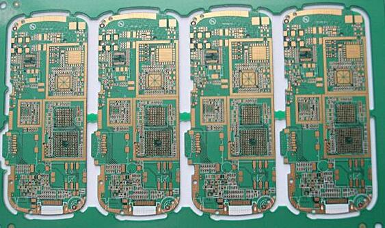
проектирование PCB project check list
1. Check the rationality and correctness of the schematic diagram;
2. Check the correctness of the component package of the schematic diagram;
3. The distance between strong and weak current and the distance between isolated areas;
4. Corresponding inspection of the schematic diagram and PCB diagram to prevent the loss of the network table;
5. Whether the package of the component is consistent with the actual product;
6. Is the placement of the components appropriate:
A. Whether the components are easy to install and disassemble;
B. Whether the temperature sensitive element is too close to the heating element;
C. Whether the distance and direction of the components that can generate mutual inductance are appropriate;
D. Whether the placement between the connectors is smooth;
E. Easy to plug and unplug;
F. Input and output;
G. Strong current and weak current;
H. Whether digital and analog are interlaced;
I. Arrangement of elements on the upwind side and downwind side;
7. Whether the directional component has been wrongly flipped instead of rotated;
8. Whether the mounting holes of the component pins are suitable and whether it is easy to insert;
9. Check whether the empty pin of each component is normal and whether it is a missing line;
10. проверить отверстие на верхнем и нижнем этажах одного и того же сетевого стола, and the pads are connected through the holes to prevent disconnection and ensure the integrity of the circuit;
11. Check whether the characters on the upper and lower layers are placed correctly and reasonably, не вставлять компонент для перезаписи символов, so as to facilitate the operation of welding or maintenance personnel;
12. The connection of the very important upper and lower layer lines should not only be connected with the pads of the in-line components, it is best to use vias to connect;
13. The arrangement of power and signal wires in the socket should ensure signal integrity and anti-interference;
14. Pay attention to the proper ratio of pads and solder holes;
15. The plugs should be placed on the edge of the панель PCB as much as possible and easy to operate;
16. Check whether the component label matches the component, and the components should be placed in the same direction as possible and placed neatly;
17. Without violating the design rules, the power and ground wires should be as thick as possible;
18. в нормальных условиях, the horizontal line is used on the upper layer and the vertical line is used on the lower layer, and the chamfer is not less than 90 degrees;
19. размер и распределение установленных отверстий на PCB, and minimize the bending stress of the PCB;
20. обратите внимание на вертикальное распределение элементов на PCB, обратите внимание на форму и размер PCB, чтобы обеспечить простоту сборки;