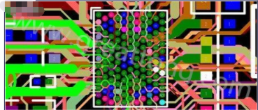
多層設計前 プリント回路基板, the designer needs to first determine the requirements of electromagnetic compatibility (EMC), 回路基板の大きさによって, 回路基板の大きさ, 回路基板の大きさ, そして、回路基板のサイズ. 使用する回路基板構造を決定する, それで, 4層を使用するかどうかを決める, 6層, 又はより一層の回路基板. 必要な層の数を決定した後, 内部電気層をどこに配置し、どのようにこれらの層に異なる信号を分配するかを決定する. これは 多層PCB スタック構造. 積層構造はPCB基板のEMC性能に影響する重要な因子である. 電磁妨害を抑制する重要な手段このセクションでは、関連するコンテンツを紹介します 多層PCB ボードスタック構造.

1. The selection of layers and the principle of superposition
There are many factors to consider when determining the stack-up structure of a 多層PCB. 配線に関して, より多くの層, 配線により良い, しかし、より多くの層, 配線により良い. メーカー向け, 積層構造が対称であるか否かはPCB基板製造時の留意点である. 積層構造が対称であるかどうかは、基板のコスト及び困難である, また、積層構造の対称性も増加する. したがって, 層数の選択は様々な局面を考慮する必要がある. バランスを達成する必要性. 経験豊富なデザイナー, コンポーネントのプリレイアウト完了後, キー解析はPCBのルーティングボトルネックで行われる. コンポーネントのプリレイアウト完了後, ツールは、回路基板の配線密度を分析するそれから、信号線を差動線のような特別な配線要件と統合する, 特別な配線要件を持つ高感度信号線, 差動回線や他のEDAツールなどの回路基板を分析する. 特別な配線密度要件を持つ信号線の数とタイプ, 差動線のような, 敏感な信号線, etc., 信号層の層数を決定する, そうすると、電源のタイプに従うシグナル・レイヤーのレイヤーのナンバーを決定する電源タイプ別, 内部電気層の数を決定するためのアイソレーションと抵抗の干渉条件. 信号層の層数を決定する, 内部電気層の数は、電源の種類に応じて決定される, アイソレーションと干渉妨害要件. このように, 回路基板全体の層の数は基本的に決定される. 回路基板の層の数を決定した後, 次の仕事は合理的に各層上の回路の配置順序を手配することである.
(1) The signal layer should be adjacent to an inner electric layer (internal power supply ground layer), そして、内部層の大きな銅膜を使用して、信号層22のシールドを提供する.
(2) The internal power supply layer and the ground layer should be tightly coupled, それで, the thickness of the medium between the internal power supply layer and the ground layer should be compared) The internal power supply layer and the ground layer should be tightly coupled, それで, 小さい値, 電源層と接地層との間の容量を増加させ、共振周波数を増加させる. 小さい値は、電力面と接地面との間の静電容量を増加させ、共振周波数を増加させる. (3) The high-speed signal transmission layer in the circuit should be a signal intermediate layer and sandwiched between two inner electrical layers. このように, つの内部電気層の銅膜は、高速信号伝送用の電磁遮蔽を提供することができる, それと同時に, 高速信号の放射は、2つの内部電気層の間で効果的に制限され得る, 外部の干渉を起こさないように.
(4) Avoid two signal layers directly adjacent to each other. クロストークは隣接する信号層の間で容易に導入される, 回路故障の結果つの信号層の間のグランドプレーンを加えることは、効果的にクロストークを避けることができる.
(5) Multiple grounded inner electrical layers can effectively reduce the ground impedance; for example, A信号層とB信号層は別々の接地面を使用する, 共通モード干渉を効果的に低減できる.
(6) Taking into account the symmetry of the layer structure.
2. Commonly used stacked structure
The following is an example of a 4-layer board to illustrate how to optimize the arrangement and combination of various stacked structures: For commonly used 4-layer boards, there are the following stacking methods (from top to bottom):
(1) Siganl_1 (Top), GND (Inner_1), POWER (Inner_2), Siganl_2 (Bottom).
(2) Siganl_1 (Top), POWER (Inner_1), GND (Inner_2), Siganl_2 (Bottom).
(3) POWER (Top), Siganl_1 (Inner_1), GND (Inner_2), Siganl_2 (Bottom).
明らかに, オプション3は、パワープレーンとグランドプレーンとの間の有効な結合を欠いて、使用してはならない. では、オプション1とオプション2をどのように選びますか? 一般に, デザイナーは、4層板の構造としてオプション1を選ぶでしょう. 理由は、オプション2を使用することはできません, しかし、一般的なPCBボードはトップ層にコンポーネントを置くだけです, したがって、オプション1を使うのがより適切です. しかし, コンポーネントが上部と下部の両方に配置される必要がある場合, また、内部電源層と接地層との間の誘電体膜厚は大きく、結合が悪い, どの層に信号線が少ないかを検討する必要がある. スキーム1, 下層には信号線が少ない, そして、大面積銅フィルムは、パワー層と結合するために用いることができる反対に, コンポーネントが主に底層に配置されるなら, スキーム2はボードを作るために使用されるべきです. 4層板の積層構造の解析終了後, the following is an example of the combination method of the 6-layer board to illustrate the arrangement and combination of the laminated structure of the 6-layer board and the preferred method:
(1) Siganl_1 (Top), GND (Inner_1), Siganl_2 (Inner_2), Siganl_3 (Inner_3), POWER (In). スキーム1は、4層の信号層と2層の内部電力を使用する/グランドレイヤー, とより多くの信号層, 部品間の配線作業に資する, しかし、この計画の欠陥もより明白です, which are manifested in the following two aspects:
a. The power and ground layers are far apart and not fully coupled
b. The signal layer Siganl_2 (Inner_2) and Siganl_3 (Inner_3) are directly adjacent to each other, 信号分離は良くない, and crosstalk is prone to occur
(2) Siganl_1 (Top), Siganl_2 (Inner_1), POWER (Inner_2), GND (Inner_3), Siganl_3 (In).
スキーム1に比べて, スキーム2は、電源層と接地層との間に十分な結合を有する, スキーム1の上にある利点がある, but Siganl_1 (Top) and Siganl_2 (Inner_1) and Siganl_3 (Inner_4) and Siganl_4 (Bottom) signal layers directly Adjacent, 信号分離は良くない, 簡単なクロストークの問題は解決されていない. Scheme 1とScheme 2と比較して, スキーム3は、1つの信号層を縮小し、内部電気層を追加する. 配線に利用可能な層は削減されるが, this scheme solves the common defects of scheme 1 and scheme 2:
a. 電力および接地層は緊密に結合されている.
b. 各信号層は、内部電気層に直接隣接している, 他の信号層から効果的に分離される, クロストークを起こしやすい.
上記2つの例の分析を通して, 私は、読者がカスケード構造の特定の理解を持っていると信じています, しかし、場合によっては, ある計画はすべての要件を満たすことができない, 様々な設計原理の優先度を考慮する必要がある. 残念ながら, 回路基板の層設計は実際の回路の特性と密接に関連するので, 異なる回路の干渉防止性能および設計フォーカスは異なる, 実際には, これらの原則には参照のための明確な優先順位がありません. But it is certain that design principle 2 (the internal power supply layer and the ground layer should be tightly coupled design principle (the internal power supply layer and the ground layer should be tightly coupled if high-speed signals need to be transmitted in the circuit, together) needs to be satisfied first in the design., 加えて, 回路が高速信号を送信する必要があるなら, then design principle 3 (the high in the circuit needs to be satisfied first in the design, if the プリント回路基板 need to transmit high-speed signals (the high-speed signal transmission layer should be the signal middle layer, and sandwiched between two between the inner electric layers) must be satisfied. The signal transmission layer should be a signal intermediate layer and sandwiched between two inner electric layers) must be satisfied.