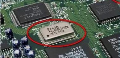
晶體振盪器的應用及合理選擇 電路板 設計
我們經常把晶體振盪器比作數位電路的覈心。 這是因為數位電路的所有工作都離不開時鐘訊號。 晶體振盪器直接控制整個系統。 如果晶體振盪器不工作,整個系統將癱瘓,囙此晶體振盪器是决定數位電路開始工作的先決條件。 我們經常談論的晶體振盪器是石英晶體振盪器和石英晶體諧振器。 它們都是利用石英晶體的壓電效應製成的。 在石英晶體的兩個電極上施加電場會導致晶體發生機械變形。 相反,如果在晶體的兩側施加機械壓力,晶體上會產生電場。 此外,這兩種現象是可逆的。 利用這一特性,在晶體兩側施加交流電壓,晶圓將產生機械振動。 同時,產生一個交變電場。 這種振動和電場一般都很小,但在一定頻率下,振幅會顯著增加。 這是壓電諧振,類似於普通LC電路諧振。

作為數位電路的覈心, 晶體振盪器如何在智慧產品中發揮作用? 用於智能家居產品,如空調, 窗簾, 安全, 監控, 等., 需要無線傳輸模塊. 他們通過藍牙等協定將模塊從一端發送到另一端, WIFI還是ZIGBEE, 或通過手機直接控制, 晶體振盪器是無線模塊中的組件. 整個系統的穩定性, 所以選擇系統中使用的晶體振盪器, 决定數位電路的成敗.
由於晶體振盪器在數位電路中的重要性, 我們在使用和使用時需要小心 設計ing:
1) There is a quartz crystal inside the crystal oscillator. 當受到外部衝擊或墜落時, 它很容易導致石英晶體不斷破裂, 這將導致晶體振盪器無法振動. 所以, 當需要時,應考慮晶體振盪器的可靠安裝 設計讓電路短路.
2) Pay attention to the welding temperature during manual welding or machine welding. 晶體振盪器對溫度很敏感, 焊接時溫度不應過高, 加熱時間應盡可能短? 合理的晶體振盪器佈局可以抑制系統輻射干擾.
1. Problem description
This product is a field 照相機, 內部分為五個部分:控制板, 感測器板, camera, SD存儲卡和電池. 外殼是一個塑膠外殼. 小板只有兩個介面:DC5V外部電源介面和用於資料傳輸的USB介面. 輻射試驗後, 發現33MHz附近存在諧波雜訊輻射問題.
2. Analyze the 問題
The shell structure of this product is made of a non-shielding 材料. 在整機測試中,只有電源線和USB電纜從外殼中引出. 是電源線和USB電纜輻射的干擾頻率? 所以, a few steps were tested separately:
(1) Only add a magnetic ring to the power cord, the test result: the improvement is not obvious;
(2) Only add a magnetic ring to the USB cable, the test result: the improvement is still not obvious;
(3) A magnetic ring is added to both the USB cable and the power cable. 測試結果:改進效果明顯, 並且總體干擾頻率降低. 從上面可以看出,干擾頻率來自兩個介面. 這不是電源介面或USB介面的問題, 但內部干擾頻率與這兩個介面耦合. 僅遮罩一個介面無法解决此問題. problem. 近場量測後, 發現干擾頻率來自32.控制板的768KHz晶體振盪器, 產生强烈的空間輻射, 囙此,周圍的記錄道和GND與32.768KHz諧波雜訊, 然後通過介面USB線和電源線的耦合輻射 . The problem with this crystal is caused by the following two problems:
a. 晶體振盪器離電路板邊緣太近, 這很容易導致晶體振盪器發出譟音.
b. 晶體振盪器下麵有一條訊號線, 這很容易導致訊號線耦合晶體振盪器的諧波雜訊.
c. 濾波裝置置於晶體振盪器下方, 濾波電容和匹配電阻不按訊號流向設定, 這使得過濾裝置的過濾效果變差.
3. Solution
According to the analysis, the following countermeasures are drawn:
(1) The filter capacitor and matching resistor of the crystal should be placed close to the CPU chip first, away from the edge of the board;
(2) Remember not to place the ground in the crystal placement area and the projection area below;
(3) The filter capacitors and matching resistors of the crystal are arranged according to the signal flow direction, and they are placed neatly and compactly near the crystal;
(4) Place the crystal close to the chip, 兩者之間的接線應盡可能短而直.
4. Conclusion
Nowadays, 許多系統晶體振盪器具有高時鐘頻率和强干擾諧波能量. 干擾諧波不僅從其輸入和輸出的兩條軌跡傳導, 但也有來自太空的輻射. 如果佈局不合理, 它可能非常强大. 雜訊輻射問題很難用其他方法解决, 所以晶體振盪器和時鐘訊號線.
預防 PCB板 設計 of crystal oscillator
(1) The coupling capacitor should be placed as close as possible to the power pin of the crystal oscillator, 以及放置順序:根據電源的方向, 將電容值從最大值放到最小值, and the
capacitance value of the capacitor is close to the power pin.
(2) The shell of the crystal oscillator must be grounded, 它可以從晶體振盪器向外輻射,還可以遮罩外部訊號對晶體振盪器的干擾.
(3) Do not wire under the crystal oscillator, 確保地面完全鋪好, 不要在晶體振盪器的300毫米範圍內佈線, 以防止晶體振盪器干擾其他接線的效能, 設備和層.
(4) The trace of the clock signal should be as short as possible, 而且線寬應該更大. 在接線長度和與熱源的距離之間找到平衡.
(5) Do not place the crystal oscillator on the edge of the PCB板. 當需要時,請特別注意這一點 設計把 PCB板.