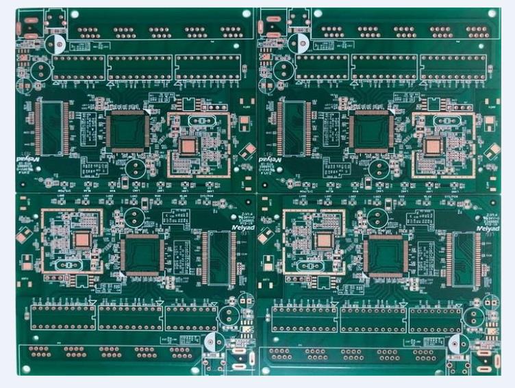
I circuiti analogici sono sistemi di circuito che gestiscono segnali continuamente variabili manipolando tensioni o correnti continue per rappresentare segnali in ingresso e produrre uscite corrispondenti. I circuiti digitali sono sistemi di circuito che gestiscono stati discreti manipolando segnali digitali (alti e bassi livelli) per rappresentare segnali in ingresso e produrre uscite corrispondenti. I circuiti analogici elaborano (amplificano o attenuano) i segnali attraverso le caratteristiche di amplificazione dei componenti, mentre i circuiti digitali elaborano i segnali attraverso circuiti logici combinati (caratteristiche di commutazione) come cancelli logici e flip-flop.
I circuiti analogici e digitali sono due sistemi di circuito importanti nell'ingegneria elettronica e svolgono un ruolo vitale nella tecnologia moderna. L'elettricità digitale è sviluppata da elettricità analogica, quindi sono diversi ma anche strettamente correlati tra loro.

Circuiti analogici
Differenza tra circuiti analogici e digitali
I circuiti analogici sono circuiti che elaborano segnali analogici; I circuiti digitali sono circuiti che elaborano segnali digitali.
Un segnale analogico è una funzione del tempo, una quantità continuamente variabile, mentre un segnale digitale è una quantità discreta. Poiché tutti i sistemi elettronici sono a dispositivi elettronici specifici, circuiti elettronici come vettore, in un'elaborazione del segnale, acquisizione del segnale, recupero del segnale sono segnali analogici, solo la parte centrale dell'elaborazione del segnale è elaborazione digitale. Nello specifico, i circuiti analogici si occupano principalmente di segnali analogici, non cambiano con il tempo, il dominio del tempo e il dominio del valore sono segnali continui, come i segnali vocali. I segnali digitali, al contrario, stanno cambiando, elaborazione digitale del segnale compreso il campionamento del segnale, la quantizzazione del segnale, la codifica del segnale.
Prendiamo un semplice esempio:
Per venire da una distanza da un suono piccolo a grande, con modulazione di ampiezza, trasmissione del segnale analogico (di conseguenza, i circuiti analogici dovrebbero essere utilizzati), allora l'ampiezza del segnale sarà sempre più nel processo di trasmissione, perché è nelle caratteristiche di ampiezza dei segnali elettrici per simulare il suono delle caratteristiche della forza del debole.
Tuttavia, se la trasmissione del segnale digitale, dovremmo utilizzare un codice, ogni livello di dimensione del suono corrisponde a un codice, nell'ingresso sonoro, ogni volta che prendete un campione, il codice corrispondente sarà trasmesso fuori. Si può vedere che non importa quanti livelli il suono è diviso in, non importa quanto alta sia la frequenza di campionamento, c'è ancora una perdita per il suono originale in questo modo. Tuttavia, questa perdita può essere compensata aumentando la frequenza di campionamento, che è teoricamente superiore al doppio della frequenza del segnale originale può essere completamente ripristinata.
I livelli dei circuiti digitali sono standardizzati, i circuiti analogici no.
Collegamento tra circuiti analogici e digitali
Il circuito analogico è quello di alimentare il circuito digitale mentre completa l'esecuzione dell'attuatore.
Nei circuiti analogici e digitali, i segnali sono espressi in modo diverso. Le operazioni che possono essere eseguite su segnali analogici, come amplificazione, filtraggio e limitazione, possono essere eseguite su segnali digitali. Infatti, tutti i circuiti digitali sono fondamentalmente circuiti analogici, e i loro principi elettrici di base, sono gli stessi di quelli dei circuiti analogici. Un semiconduttore complementare ad ossido di metallo è costituito da due tubi analogici ad effetto campo ad ossido di metallo, la cui struttura simmetrica e complementare lo rende giusto per gestire livelli logici digitali alti e bassi. Tuttavia, i circuiti digitali sono progettati con l'obiettivo di essere utilizzati per elaborare segnali digitali, e il rumore di quantizzazione può risultare se segnali analogici arbitrari sono forzati senza ulteriore elaborazione.
Una funzione che rappresenta il valore di un segnale in un insieme di tempi discreti è chiamata segnale a tempo discreto. Questo perché i segnali a tempo discreto più comunemente incontrati sono segnali analogici campionati a intervalli regolari (e talvolta non uniformi) nel tempo. I termini "tempo discreto" e "digitale" sono spesso usati per descrivere lo stesso segnale. Alcune delle teorie dei segnali a tempo discreto si applicano anche ai segnali digitali.
Come realizzare la funzione dei circuiti analogici e digitali
Circuiti analogici e circuiti digitali sono anche portatori di cambi di segnale, circuiti analogici nel circuito dell'amplificazione e riduzione del segnale sia attraverso le caratteristiche di amplificazione dei componenti per raggiungere l'operazione, mentre i circuiti digitali è la trasmissione del segnale sia attraverso le caratteristiche di commutazione per raggiungere l'operazione.
Nei circuiti analogici, i cambiamenti di tensione, corrente, frequenza e periodo sono reciprocamente limitati, mentre nei circuiti digitali i cambiamenti di tensione, corrente, frequenza e periodo nel circuito sono discreti.
I circuiti analogici possono funzionare ad alta corrente e ad alta tensione, mentre i circuiti digitali funzionano solo a bassa tensione, a basso consumo energetico corrente per completare o generare segnali di controllo stabili.
Con il progresso della tecnologia e l'ascesa del deep learning, circuiti analogici e circuiti digitali sono sempre più utilizzati in settori come l'intelligenza artificiale, l'apprendimento automatico e l'Internet delle cose.