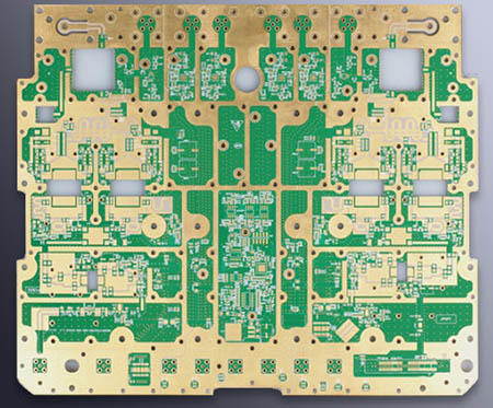
多層回路ボード工場のPCB放熱技術
電子機器が作動中, それは多くの熱を生成します, 装置の内部温度を急速に上昇させる. 熱が時間に消散されないならば, 機器は加熱し続ける, 過熱のために装置が故障する, そして、電子機器の信頼性が低下する. したがって, 熱分解処理を行うことは非常に重要である PCBボード バッチメーカーの 多層回路基板.
一つ. の温度上昇因子の解析 プリント回路基板
多層回路基板の温度上昇の直接原因は、回路内の消費電力デバイスの存在による, そして、電子デバイスは、あらゆる程度に電力消費を有する, そして、加熱強度は、消費電力の大きさによって変化する.
における温度上昇の2つの現象 プリント回路基板:
(1) Local temperature rise or large area temperature rise;
(2) Short-term temperature rise or long-term temperature rise.
Aの熱消費電力を解析するとき PCB多層回路基板, それは、一般的に以下の局面から分析されます.
1. Electrical power consumption
(1) Analyze the power consumption per unit area;
(2) Analyze the distribution of power consumption on 多層回路基板.
2, the structure of the printed circuit board
(1) The size of the printed circuit board;
(2) Printed circuit board materials.
3, thermal convection
(1) Natural convection;
(2) Forced cooling convection.
4, heat conduction
(1) Install a radiator;
(2) Conduction of other installation structures.
5. How to install the printed circuit board
(1) Installation method (such as vertical installation, horizontal installation);
(2) The sealing condition and the distance from the case.
6, heat radiation
(1) The emissivity of the printed circuit board surface;
(2) The temperature difference between the printed circuit board and adjacent surfaces and their absolute temperature;
The analysis of the above factors from the PCB circuit board proofing manufacturers is an effective way to solve the temperature rise of the printed board. これらの要因はしばしば製品とシステムにおいて互いに関連し、依存している. ほとんどの要因は、実際の状況に応じて分析されるべきである. 特定の実情によると, 温度上昇や消費電力などのパラメータをより正確に計算することができます.

2. Heat dissipation method of multilayer circuit board
1. 高発熱装置プラスラジエーター, heat conducting plate
When a small number of components in the PCB circuit board generate a large amount of heat (less than 3), ラジエータまたはヒートパイプを加熱コンポーネントに加えることができる. 温度が下がることができないとき, 放熱器効果を高めるためにファン付きラジエーターを使用することができる. When the number of heating devices is large (more than 3), a large heat dissipation cover (board) can be used, これは、PCB上の加熱装置の位置と高さによってカスタマイズされた特別なヒートシンクであるか、または異なる部品高さ位置を切り出す大きな平坦なヒートシンクである. 放熱カバーは、コンポーネント100の表面に一体的に座屈している, そして、それは熱を放散するために、各々の構成要素と接触しています. しかし, 部品の組立と溶接の間の高さの整合性が悪いので、熱効果は良くない. 通常, 熱放散効果を改善するために、柔らかい熱相変化熱パッドがコンポーネントの表面に加えられる.
2. Use reasonable wiring design to realize heat dissipation
Because the resin in the sheet has poor thermal conductivity, 銅箔のラインと穴は熱の良い導体である, 銅箔の残留率の増加と熱伝導孔の増加は熱放散の主な手段である.
多層回路基板の放熱能力を評価するために, it is necessary to calculate the equivalent thermal conductivity (nine eq) of a composite material composed of various materials with different thermal conductivity-an insulating substrate for a multilayer circuit board.
3, heat dissipation through the PCB circuit board itself
At present, 広く使用される多層回路基板材料は銅クラッドである/エポキシガラス布基板又はフェノール樹脂ガラスクロス基板, そして、少量のペーパーベースの銅のクラッド板は、使われます. これらの基板は優れた電気的性質及び加工特性を有するが, 彼らは熱放散が悪い. 高発熱部品のための放熱経路として, PCB自体の樹脂からの熱が熱を起こすのを期待することはほとんど不可能である, しかし、コンポーネントの表面から周囲の空気まで熱を放散させる. しかし, 電子製品は部品の小型化時代に入った, 高密度実装, 高発熱アセンブリ, それは、熱を放散させるために非常に小さい表面積で構成要素の表面に頼るのに十分ではありません. 同時に, QFPやBGAなどの表面実装部品の大規模使用により, コンポーネントによって生成された熱は、PCB回路基板に大量に転送される. したがって, 放熱を解決する最良の方法は、加熱素子と直接接触するPCB自体の放熱能力を向上させることである. 板は伝導するか、放射する.
4. The temperature-sensitive device is best placed in the lowest temperature area (such as the bottom of the device). 加熱装置の上に直接置かないこと. 水平面に複数のデバイスを停滞させるのがベストです.
5. 水平方向に, 高電力デバイスは、熱伝達経路を短くするためにプリント板のエッジの近くに配置される垂直方向に, これらのデバイスが動作するとき、高出力デバイスは他のデバイスの温度を下げるために可能な限りプリントボードの最上部に配置される. 衝撃.
6. 熱放散のために最高の位置の近くで最も高い消費電力と熱発生で装置を配置してください. プリント基板の角部と周縁部に高発熱デバイスを配置しない, ヒートシンクが近くに置かれない限り. 電源抵抗器の設計, 可能な限り大きなデバイスを選択してください, そして、プリント基板のレイアウトを調整するとき、それは熱放散のために十分なスペースを作る.
7. 同じプリント回路基板上のデバイスは、それらの熱量値および熱放散度に応じてできるだけ配置されるべきである. Devices with small calorific value or poor heat resistance (such as small signal transistors, 小規模集積回路, 電解コンデンサ, etc.) At the uppermost flow (inlet) of the cooling airflow, devices with large heat or heat resistance (such as power transistors, 大規模集積回路, etc.) are placed at the furthest downstream of the cooling airflow.
8. 装置内のプリント回路基板の放熱は主に空気流に依存する, したがって、空気流路は設計中に研究されるべきである, そして、デバイスまたはプリント回路基板は、合理的に構成されなければならない. 空気が流れるとき, 常に抵抗の低い場所で流れる傾向がある, それで、プリント回路基板の上で装置を構成するとき, ある地域に大きな空域を残すのを避ける. 複数の構成 プリント回路基板 全体のマシンでも同じ問題に注意を払う必要がありますて.
9. 避けてくださいホットスポットの濃度 PCBボード, 均等に力を分配する PCBボード できるだけ, の表面温度性能を保つ PCBボード 均一で一貫性のある. 設計プロセス中に厳密な均一分布を達成することは困難である, しかし、ホットスポットが回路全体の正常な動作に影響を及ぼすのを防ぐために、高出力密度を有する領域を避ける必要がある. できれば, 印刷回路の熱効率を解析する必要がある. 例えば, 専門家に追加された熱効率指標分析ソフトウェアモジュール PCBボード 設計ソフトウェアは設計者が回路設計を最適化するのを助ける.
10. 自由対流空気冷却を採用する装置について, it is best to arrange integrated circuits (or other devices) vertically or horizontally.
11. 高放熱デバイスを基板と接続する場合, それらの間の熱抵抗はできるだけ減少させるべきである. 熱特性要件をより良く満たすために, some thermal conductive materials (such as a layer of thermally conductive silica gel) can be used on the bottom surface of the chip, そして、デバイスが熱を放散するために、ある接触面積を維持することができる.
12. Connection between device and substrate:
(1) Try to shorten the lead length of the device;
(2) Choose a device with more pins;
(3) When selecting high-power devices, リード材料の熱伝導率を考慮すべきである. できれば, リードの最大のクロスセクションを選択してください.
13. Package selection of the device:
(1) When considering thermal design, pay attention to the package description of the device and its thermal conductivity;
(2) Consider providing a good heat conduction path between the substrate and the device package;
(3) Air partitions should be avoided in the heat conduction path. この場合は, 充填用に熱伝導性材料を使用することができる.