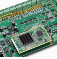
Printed circuit board (PCB) is the support of circuit components and devices in electronic products. It provides circuit components and devices
Electrical connection between. 電気技術の急速な発展, PCBの密度が高くなってきている. 品質 PCB設計 反干渉能力に大きな影響を与える. したがって, に PCB設計. 一般的な原則 PCB設計 は、, そして、干渉防止設計の要件は満たさなければなりません. 電子回路の最高の性能を得る, 部品のレイアウトと配線のレイアウトは非常に重要である. 良質で低コストでPCBを設計するために. The following general principles should be followed:

1. Layout
First, PCBサイズ. PCBサイズが大きすぎるとき, 印刷ラインは長くなる, インピーダンスが増える, アンチノイズ能力が低下する, そして、コストが増加しますPCBサイズが小さすぎるなら, 放熱は良くない, 隣接する行は簡単に妨害される. PCBサイズの決定の後. 次に、特殊なコンポーネントの位置を決定します. 最後に, 回路の機能単位に従って, 回路の全ての構成要素がレイアウトされている.
2 .高周波成分間の配線をできるだけ短くし、分布パラメータや相互電磁干渉を低減しようとする。干渉に影響されやすいコンポーネントは、あまりにも近接している必要はありませんし、入力および出力コンポーネントをできるだけ遠くに保つ必要があります。
3. ある部品またはワイヤの間に高い電位差があるかもしれない, それで、彼らの間の距離は、事故を避けるのを避けるために増加しなければなりません.
外部短絡回路. 高電圧の部品は、デバッグ中に手で容易に到達できない場所でできるだけ配置されるべきである.
4. 15 g以上の重さは、ブラケットで固定されて、それから溶接されなければなりません. 大きいもの, ヘビー, and generate a lot of heat
The components should not be mounted on the printed circuit board, しかし、完全なマシンのシャーシ底板に取り付けるべきです, 放熱問題は考慮すべきである. Thermal element
Keep away from heating elements.
5. ポテンショメータのような調節可能な部品のレイアウトのために, 調整可能なインダクタンスコイル, 可変コンデンサ, マイクロスイッチ, etc., マシン全体の構成を考慮する必要があります.
制度要件. それが機械の中で調節されるならば, それは、調整に便利なプリント回路基板に置かれるべきですそれが機械の外で調整されるならば, its position should be the same as
The position of the adjusting knob on the panel of the chassis is suitable.
6. プリント基板と固定ブラケットの位置決め穴によって占められる位置は予約されなければならない.
回路の機能単位によれば. 回路のすべての構成要素をレイアウトするとき, the following principles must be met:
1. 回路流に従って各機能回路ユニットの位置を調整する, そのため、レイアウトは信号循環に便利です, and
Keep the signal in the same direction as possible.
2. 各々の機能回路の中心コンポーネントを中心として、それの周りにレイアウトしてください. Components should be uniform and neat
Arranged neatly and compactly on the PCBボード. コンポーネント間のリードと接続の最小化と短縮.
3. 高周波で動作する回路, コンポーネント間の分散パラメータを考慮する必要があります. The general circuit should be used as much as possible
The components are arranged in parallel. このように, 美しいだけでなく. と簡単にインストールし、溶接. 大量生産.
4. 回路基板の縁部に配置された構成要素は、一般に、回路基板12の縁部から2 mm以上離れている. The best shape of the circuit board
It is a rectangle. アスペクト比は3 : 2から4 : 3です. 回路基板のサイズが200 x 150 mmより大きいとき. 回路基板の機械的強度を考慮すべきである.
7. wiring
The principle of wiring is as follows:
1. 入出力端子に使用されるワイヤは、互いに隣接しているのを避けるようにしなければならない. フィードバック結合を避けるためにワイヤ間に接地線を加えることが最善である.
2. プリント配線の最小幅は、ワイヤと絶縁基板との間の接着強度およびそれらを流れる電流値によって主に決定される.
確かに. 銅箔の厚さが0であるとき.0 mmと幅は1~1です.5 mm. 2 Aの電流で, 温度は3°C以上ではない, したがって. 1の線幅.5 mmは要件を満たすことができる. 集積回路, 特にデジタル回路, 0の線幅.02~0.3 mmは通常選択される. もちろん, できるだけ, できるだけ広い線として使う. 特に電源コードと接地線. ワイヤの最小間隔は、主にワイヤ間の最悪の絶縁抵抗及び降伏電圧によって決定される. 集積回路, 特にデジタル回路, プロセスが許す限り, 間隔は、5 mm.
4. プリント基板の配線における以下の問題点に注目してください, the wiring width of the power line is â¥1mm; the power line
As close as possible to the ground wire, the power supply and ground on the entire printed board should be distributed in a "well" shape so that the distributed wire current can reach
To balance; a zero-volt line must be provided for analog circuits; to reduce crosstalk between lines, 必要なら, increase the number of printed lines
Care about the distance; insert some zero-volt wires as isolation between the lines; the plugs of the printed circuit should also be arranged with more zero-volt wires as
Isolation between lines; pay special attention to the size of the wire loop in the current flow; if possible, enter the control line (on the printed board)
Connect R-C decoupling at the mouth to eliminate the interference factors that may appear in the transmission; the line width on the printed arc should not change suddenly, and the wire should not suddenly corner (â¥90 degrees).
5. Pad
The pad is larger than the lead diameter of the device. しかし, パッドが大きすぎるならば, 偽のはんだを作るのは簡単だ. The outer diameter of the pad D is generally not less than
(d+1.2)mm, ここでdはリード直径である. 高密度ディジタル回路, the minimum diameter of the pad can be (d+1.0) mm.
上記の一般的な原則の導入です PCB設計. IPCBも提供されて PCBメーカー とPCB製造技術.