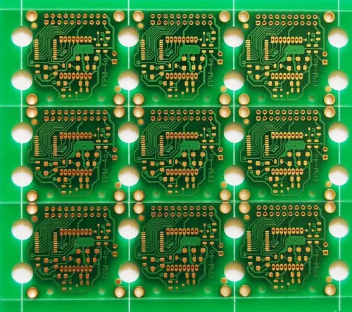
這個 concept of "Layer"
Similar to the concept of "layer" introduced in word 過程ing or many other software to realize the nesting and synthesis of graphics, 文字, 顏色, 等., Protel的“層”不是虛擬的, 但實際印製板資料本身在各種銅箔層中. 現今, 由於電子電路元件安裝密集. 抗干擾和接線等特殊要求. The PCB印製板 在一些較新的電子產品中,不僅有用於佈線的上下側, 還有可以在電路板中間進行特殊處理的層間銅箔. 例如, 現時電腦主機板使用的大部分印製板資料都在4.層以上. 因為這些層比較難處理, they are mostly used to set up the power wiring layers with simpler wiring (such as Ground Dever and Power Dever in the software), and often use large-area filling methods for wiring (such as ExternaI P1a11e and Fill in the software). ). 上下表面層和中間層需要連接的地方, 軟件中提到的所謂“過孔”用於通信. 根據上述解釋, 理解“多層焊盤”和“佈線層設定”的相關概念並不困難. 舉個簡單的例子, 許多人已經完成了接線,發現許多連接的端子在列印出來時沒有焊盤. 事實上, 這是因為他們在添加設備庫時忽略了“層”的概念,而沒有自己繪製和打包. The pad characteristic is defined as a multi-layer (Mulii-Layer). 需要注意的是,一旦選擇了印製板的層數, 確保關閉那些未使用的層,以避免造成麻煩.

2. Via
In order to connect the lines between the layers, 在每層需要連接的導線的文匯處鑽一個普通孔, 哪個是通孔. 在這個過程中, 通過化學沉積在通孔孔壁的圓柱表面上鍍一層金屬,以連接需要連接到中間層的銅箔, 通孔的上下側做成普通的焊盤形狀, 它可以直接連接到上下線路, 或未連接.
一般來說, there are the following principles for the treatment of vias when designing a circuit:
(1) Use vias as little as possible. 一旦選擇過孔, 一定要處理好它和周圍實體之間的差距, 特別是線路和過孔之間的間隙,這些間隙不與中間層中的過孔相連,容易被忽略. 通過在“Via minimization”子功能表中選擇“on”項,可以自動解决自動佈線問題. (2) The larger the current-carrying capacity required, 所需過孔的尺寸越大. 例如, 用於將電源層和接地層連接到其他層的過孔將更大.
3. Silk screen layer (Overlay)
In order to facilitate the installation and maintenance of the circuit, 所需的徽標圖案和文字程式碼列印在印製板的上下表面上, 如部件標籤和標稱值, 部件輪廓形狀和製造商標誌, 生產日期, 等. 當很多初學者設計絲印層的相關內容時, 他們只注意文字符號的整齊美觀的放置, 忽略實際PCB效應. 在他們設計的印製板上, 這些字元要麼被元件堵塞,要麼侵入焊接區域並擦掉, 一些部件標記在相鄰部件上. 這種不同的設計將給裝配和維護帶來很多好處. 不方便的. 絲印層上文字佈局的正確原則是:“不含糊, 縫線一目了然, 美麗大方“.
4. The particularity of SMD
There are a large number of SMD packages in the Protel package library, 那就是, 表面焊接設備. 除了尺寸小之外,這種器件的最大特點是銷孔的單側分佈. 因此, 選擇此類設備時, it is necessary to define the surface of the device to avoid "missing pins (Missing Plns)". 此外, 此類構件的相關文字注釋只能沿構件所在的表面放置.
5. Grid-like filling area (External Plane) and filling area (Fill)
Just like the names of the two, 網絡填充區是將大面積銅箔加工成網絡, 填充區域僅保持銅箔完整. 在設計過程中,初學者通常在電腦上看不到兩者之間的差异, 事實上, 只要你放大, 你一眼就能看到. 正是因為在正常情况下不容易看出兩者之間的差异, 所以在使用它的時候, 區分兩者更為粗心. 應該強調的是,前者具有很强的抑制電路特性中高頻干擾的效果, 並且適合需要. 大面積填充的地方, 特別是當某些區域用作遮罩區域時, 分區區域, 或大電流電源線特別適合. 後者主要用於需要較小區域的地方,如一般線路末端或轉彎區域.
6. Pad
The pad is the most frequently contacted and most important concept in PCB設計, 但是初學者往往忽略了它的選擇和修改, 並在設計中使用圓形墊板. 部件襯墊類型的選擇應綜合考慮形狀, 大小, 佈局, 振動和加熱條件, 和組件的力方向. Protel在套裝軟體庫中提供了一系列不同尺寸和形狀的焊盤, 例如圓形, 廣場, 八角形, 圓形和定位墊, 但有時這還不够,需要自己編輯. 例如, 用於產生熱量的墊子, 承受更大的壓力, 和是當前的, 它們可以設計成“淚滴狀”. 在熟悉的彩電PCB線路輸出變壓器的pin焊盤設計中, 許多製造商正處於這種形式. 一般來說, 除此之外, the following principles should be considered when editing the pad by yourself:
(1) When the length of the shape is inconsistent, the difference between the width of the wire and the specific side length of the pad should not be too large;
(2) It is often necessary to use asymmetric pads with asymmetrical length when wiring between component lead angles;
(3) The size of each component pad hole should be edited and determined separately according to the thickness of the component pin. 原理是孔的大小為0.2到0.比銷直徑大4 mm.
7. Various types of membranes (Mask)
These films are not only indispensable in the PCB生產 process, 也是構件焊接的必要條件. 根據“膜”的位置及其功能, the "membrane" can be divided into component surface (or welding surface) soldering mask (TOp or Bottom) and component surface (or soldering surface) solder mask (TOp or BottomPaste Mask). 顧名思義, 焊接膜是應用於焊盤以提高可焊性的膜, 那就是, 綠色板上的淺色圓點略大於墊板. 焊接掩模的情况正好相反, 用於使成品板適應波峰焊和其他焊接方法, 要求板上非焊盤處的銅箔不能鍍錫. 因此, 除焊盤外,所有零件都必須塗上一層油漆,以防在這些零件上塗錫. 可以看出,這兩種膜是互補關係. 從這次討論中, 在選單中確定“阻焊板放大”等項目的設定並不困難.
8 Flying line
The flying line has two meanings:
A rubber band-like network connection used for observation during automatic routing. 通過網絡錶導入組件並進行初步佈局後, 您可以使用“Show”命令查看佈局下網絡連接的交叉狀態, 並繼續調整組件的位置,使該交叉最小化,以獲得最大的自動路由速率. 這一步非常重要. 可以說是磨刀而不是誤切木頭. 這需要更多的時間和價值! 此外, 自動路由已結束, 還有哪些網絡尚未部署, 您也可以使用此函數來查找. 在發現網絡尚未部署後, 您可以使用手動補償, 如果你不能補償, 你需要使用“flying line”的第二個意思, 這是在未來的印刷電路板電線是用來連接這些網絡. 應該承認的是,如果電路板是批量生產的自動線生產, 該飛線可以設計為電阻為0歐姆、焊盤間距均勻的電阻元件.