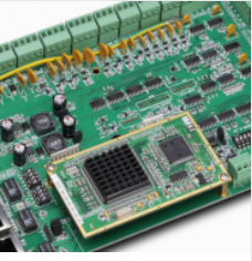
Printed circuit board (PCB) is the support of circuit components and devices in electronic products. It provides circuit components and devices
Electrical connection between. 隨著電子技術的飛速發展, 印刷電路板的密度越來越高. 質量 PCB設計 對抗干擾能力有很大影響. 因此, 在 PCB設計. 一般原則 PCB設計 必須遵守, 並且必須滿足抗干擾設計的要求. 獲得電子電路的最佳效能, 元件的佈局和導線的佈局非常重要. 為了設計出高品質、低成本的PCB. The following general principles should be followed:

1. Layout
First, 考慮PCB尺寸. 當PCB尺寸過大時, 列印的線條會很長, 阻抗將新增, 抗雜訊能力會降低, 成本會新增; 如果PCB尺寸太小, 散熱不好, 相鄰線路容易受到干擾. 確定PCB尺寸後. 然後確定特殊部件的位置. 最後, 根據電路的功能單元, 電路的所有部件都已佈置好.
2、儘量縮短高頻元件之間的接線,儘量減少其分佈參數和相互電磁干擾。 易受干擾的部件不應彼此靠得太近,輸入和輸出部件應盡可能遠離。
3. 某些部件或導線之間可能存在高電位差, 囙此,應新增它們之間的距離,以避免放電事故.
外部短路. 高壓部件應盡可能佈置在調試過程中手不易觸及的地方.
4. 重量超過15g的部件應用支架固定,然後焊接. 那些是大的, 重的, and generate a lot of heat
The components should not be mounted on the printed circuit board, 但應安裝在整機底盤底板上, 應考慮散熱問題. Thermal element
Keep away from heating elements.
5. 用於可調部件(如電位計)的佈局, 可調電感線圈, 可變電容器, 微動開關, 等., 應考慮整個機器的配寘.
機构要求. 如果在機器內部進行調整, 應放置在印刷電路板上便於調整的位置; 如果在機器外部進行調整, its position should be the same as
The position of the adjusting knob on the panel of the chassis is suitable.
6. 應保留印製板定位孔和固定支架佔用的位置.
根據電路的功能單元. 在佈置電路的所有部件時, the following principles must be met:
1. 根據電路流程安排每個功能電路單元的位置, 這樣佈局便於訊號流通, and
Keep the signal in the same direction as possible.
2. 以每個功能電路的核心部件為中心,圍繞其進行佈局. Components should be uniform and neat
Arranged neatly and compactly on the PCB板. 最小化並縮短部件之間的導線和連接.
3. 對於高頻工作的電路, 應考慮組件之間的分佈參數. The general circuit should be used as much as possible
The components are arranged in parallel. 以這種管道, 不僅美麗. 易於安裝和焊接. 易於批量生產.
4. 位於電路板邊緣的部件與電路板邊緣的距離通常不小於2mm. The best shape of the circuit board
It is a rectangle. 縱橫比為3:2到4:3. 當電路板尺寸大於200x150mm時. 應考慮電路板的機械強度.
7. wiring
The principle of wiring is as follows:
1. 用於輸入和輸出端子的導線應儘量避免相互平行. 最好在導線之間添加地線,以避免迴響耦合.
2. 印刷導線的最小寬度主要由導線和絕緣基板之間的粘附强度以及流經它們的電流值决定.
當然. 當銅箔的厚度為0時.05毫米,寬度1~1.5mm. 電流為2A, 溫度不會高於3℃, 因此. 導線寬度為1.5mm可滿足要求. 對於集成電路, 尤其是數位電路, 導線寬度為0.02~0.通常選擇3mm. 當然, 盡可能長, 使用盡可能寬的線. 尤其是電源線和地線. 導線的最小間距主要由最壞情况下的絕緣電阻和導線之間的擊穿電壓决定. 對於集成電路, 尤其是數位電路, 只要過程允許, 間距可以小到5-8mm.
4. 印刷電路板佈線時應注意以下問題:專用零電壓線, the wiring width of the power line is 1mm; the power line
As close as possible to the ground wire, the power supply and ground on the entire printed board should be distributed in a "well" shape so that the distributed wire current can reach
To balance; a zero-volt line must be provided for analog circuits; to reduce crosstalk between lines, 如有必要, increase the number of printed lines
Care about the distance; insert some zero-volt wires as isolation between the lines; the plugs of the printed circuit should also be arranged with more zero-volt wires as
Isolation between lines; pay special attention to the size of the wire loop in the current flow; if possible, enter the control line (on the printed board)
Connect R-C decoupling at the mouth to eliminate the interference factors that may appear in the transmission; the line width on the printed arc should not change suddenly, and the wire should not suddenly corner ( 90 degrees).
5. Pad
The pad is larger than the lead diameter of the device. 然而, 如果墊子太大, 很容易形成假焊料. The outer diameter of the pad D is generally not less than
(d+1.2)mm, 其中d是導線直徑. 用於高密度數位電路, the minimum diameter of the pad can be (d+1.0) mm.
以上介紹了 PCB設計. Ipcb也提供給 PCB製造商 和PCB製造技術.