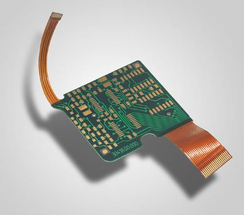
它們可以集成在一個小的 PCB電路板 用於無線數位音訊, 數位視訊資料傳輸系統, 無線遙控和遙測系統, 無線資料獲取系統, 無線網路和無線安全系統以及許多其他領域.單片射頻裝置大大方便了, 並且可以使用以下方法形成完整的無線通訊連結:.
1 Potential conflicts between digital circuits and analog circuits
If the analog circuit (RF) and the digital circuit (microcontroller) work separately, 它們可能很好用, 但一旦它們被放在同一塊板上,並由同一電源供電, 整個系統可能不穩定 . This is mainly because the digital signal frequently swings between the ground and the positive power supply (3. V in size), 而且週期很短, 通常在ns級別. 由於振幅較大,開關時間較小, 這些數位信號包含大量與開關頻率無關的高頻分量. 在類比部分, 從天線調諧環路傳輸到無線設備接收部分的訊號通常小於1mV. So the difference between the digital signal and the RF signal will be 10-6 (12.0 dB). 明顯地, 如果數位信號與射頻訊號沒有很好地分離, 微弱的射頻訊號可能會損壞, 囙此,無線設備的工作效能將惡化, 甚至完全無法工作.

2. Common problems with RF circuits and digital circuits on the same PCB
Insufficient isolation of sensitive and noisy signal lines is a common problem. 如上所述, 數位信號具有高擺幅,並含有大量高頻諧波. 如果PCB上的數位信號佈線與敏感類比信號相鄰, 高頻諧波可能通過. Sensitive nodes of RF devices are usually the phase-locked loop (PLL) loop filter circuit, external voltage-controlled oscillator (VCO) inductance, 晶體參攷訊號和天線端子, 電路的這些部分應特別小心處理.
(1) Power supply noise
Since the input/輸出信號具有幾伏的擺動, digital circuits are generally acceptable for power supply noise (less than 50 mV). 類比電路, 另一方面, 對電源雜訊非常敏感, 特別是故障電壓和其他高頻諧波. 因此, the routing of power lines on PCB containing RF (or other analog) circuits must be done more carefully than on ordinary digital boards, 應避免自動佈線. It should also be noted that a microcontroller (or other digital circuit) will suddenly draw most of the current for a short period of time during each internal clock cycle, 因為現代微控制器是在CMOS工藝上設計的. 因此, 假設微控制器以1 MHz的內部時鐘頻率運行, it will draw (pulse) current from the power supply at this frequency, 如果不採取適當的電源去耦,這將不可避免地導致電源線上的電壓故障. 如果這些電壓故障到達電路RF部分的電源引脚, 這可能會嚴重導致工作失敗, 囙此,必須確保類比電源線與數位電路區分開.
(2) Unreasonable ground wire
RF circuit boards should always have a ground plane connected to the negative side of the power supply, 如果處理不當,可能會導致一些奇怪的行為. 這對於數位電路設計者來說可能很難理解,因為大多數數位電路即使沒有接地層也能正常工作. 在射頻頻段, 即使是很短的導線也可以起到電感的作用. 粗略計算, 每毫米長度的電感約為1 nH, 434 MHz下10 mm PCB線路的電感約為27Î). 沒有地平面, 大多數接地線將很長,電路將無法保證設計特性.
(3) Radiation from the antenna to other analog parts
In circuits containing RF and other parts, 這一點經常被忽視. 除了RF部分, 板上通常有其他類比電路. 例如, many microcontrollers have built-in analog-to-digital converters (ADCs) for measuring analog inputs as well as battery voltage or other parameters. If the RF transmitter's antenna is located near (or on) this PCB, 發射的高頻訊號可能到達ADC的類比輸入. 不要忘記,任何電路線路都可能像天線一樣發送或接收射頻訊號. 如果未正確處理ADC輸入, 射頻訊號可能在ADC輸入的ESD二極體中自激, 導致ADC漂移.
3. Solution A with RF circuit and digital circuit on the same PCB
Some general design and routing strategies in most RF applications are given below. 然而, 在實際應用中,遵循射頻設備的路由建議更為重要.
(1) A reliable ground plane
When designing a PCB with RF components, 應始終使用可靠的接地層. 其目的是在電路中建立一個有效的0 V電位點, 允許所有設備輕鬆解耦. 電源的0 V端子應直接連接到此接地層. 由於接地層的低阻抗, 已解耦的兩個節點之間將沒有訊號耦合. 這一點非常重要,因為電路板上多個訊號的振幅可能相差120dB. 在表面安裝PCB上, 所有訊號佈線在部件安裝表面的同一側, 地平面在另一側. The ideal ground plane should cover the entire PCB (except under the antenna PCB). 如果使用兩層以上的PCB, the ground layer should be placed on the layer adjacent to the signal layer (such as the next layer on the component side). 另一個好方法是用地平面填充訊號路由層的空白部分, 必須通過多個過孔連接到主接地層. 應注意的是,由於接地點的存在將導致其旁邊的電感特性發生變化, 必須仔細考慮電感值的選擇和電感的排列.
(2) Shorten the connection distance to the ground layer
All connections to ground planes must be kept as short as possible, and ground vias should be placed at (or very close to) the component pads. 絕不允許兩個接地訊號通過, 由於通孔連接阻抗,這可能導致兩個焊盤之間的串擾.
(3) RF decoupling
Decoupling capacitors should be placed as close to the pins as possible, 需要解耦的每個引脚都應使用電容器解耦. 使用優質陶瓷電容器, 電介質類型為“NPO”, “X7R”也適用於大多數應用程序. 應選擇理想的電容值,使其串聯諧振等於訊號頻率. 例如, 434 MHz時, 安裝在SMD上的100 pF電容器將工作良好. 在此頻率下, 電容器的容性電抗約為4Ω, 通孔的感應電抗在相同範圍內. 電容器和通孔串聯形成訊號頻率的陷波濾波器, 實現有效解耦. 868 MHz時, 33 pF電容器是理想的選擇. 除了用於射頻去耦的小值電容器之外, 還應在電源線上放置一個大值電容器,以解耦低頻. 選擇一個2.2mF陶瓷或10mF鉭電容器.
(4) Star wiring of power supply
Star wiring is a well-known trick in analog circuit design. 星形接線-電路板上的每個模塊都有來自公共電源點的自己的電源線. 在這種情況下, 星形佈線意味著電路的數位和射頻部分應該有自己的電源線,這些電源線應該在靠近集成電路的地方單獨解耦. This is a spacer from a number
Partial and efficient approach to power supply noise from the RF part. 如果雜訊嚴重的模塊放置在同一電路板上, an inductor (magnetic bead) or a small-value resistor (10 Ω) can be connected in series between the power line and the module, 必須使用至少10mF的鉭電容器. 模塊的電源去耦. 這些模塊是RS 232驅動器或開關功率調節器.
(5) Reasonable arrangement of PCB板 layout
In order to reduce the interference from the noise module and the surrounding analog parts, 電路板上每個電路模塊的佈局很重要. Sensitive modules (RF section and antenna) should always be kept away from noisy modules (microcontroller and RS 232 driver) to avoid interference.
(6) Shield the influence of RF signal on other analog parts
As mentioned above, 射頻訊號在傳輸時可能會干擾其他敏感的類比電路塊,如模數轉換器. Most problems occur in lower operating frequency bands (eg 27 MHz) and high power output levels. It is a good design practice to decouple sensitive points with RF decoupling capacitors (100p F) connected to ground.
(7) Special Considerations for On-Board Loop Antennas
The antenna can be made on the PCB as a whole. 與傳統鞭狀天線相比, 它不僅節省了空間和生產成本, 而且在機理上更穩定可靠. 按慣例, 環形天線設計用於相對較窄的頻寬, 這有助於抑制不必要的强訊號干擾接收器. It should be noted that loop antennas (like all other antennas) may receive noise capacitively coupled from nearby noisy signal lines. 它干擾接收器,也可能影響發射器的調製. 因此, 數位信號線不得在天線附近佈線, 建議在天線周圍保留自由空間. 任何靠近天線的物體都將構成調諧網絡的一部分, 使天線調離預期頻率, reducing the transmit and receive radiation range (distance). 對於所有類型的天線,都必須注意這一點, the enclosure (peripheral packaging) of the circuit board may also affect the antenna tuning. 同時, 應注意拆除天線區域的接地層, 否則天線將無法有效工作.
4 Conclusion
The rapidly developing radio frequency integrated circuits provide the possibility for engineers and technicians engaged in the design of wireless digital audio and video data transmission systems, 無線遙控器, 遙測系統, 無線資料獲取系統, 解决無線應用瓶頸的無線網路和無線安全系統. . 同時, 射頻電路的設計要求設計人員具有一定的實踐經驗和工程經驗 PCB板 設計能力.