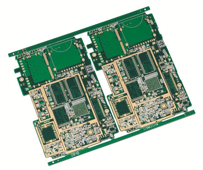
部品を合理的に配置することは、高品質PCBボードのレイアウトを設計する基本的な前提である。部品レイアウトに対する部品レイアウトの要件には、主に取り付け、力、熱、信号、見栄えが含まれます。インストールとは、特定のアプリケーションでキャビネット、筐体、スロットに回路基板をスムーズに取り付け、空間的な干渉や短絡などの事故を回避し、指定されたコネクタをキャビネットまたは筐体上の指定された位置に保持するための一連の基本的な要件です。要件私はここで詳しく述べたくありません。

1.2. 力回路基板は取り付けと作業中の各種外力と振動に耐えられるべきである。そのため、回路基板は合理的な形状を持つべきで、基板上の各種孔(ねじ孔、異形孔)の位置は合理的に配列すべきである。一般に、穴とプレートエッジとの間の距離は、穴の直径よりも少なくとも大きくなければならない。同時に、異形穴による板の脆弱な断面も十分な曲げ強度を持つべきであることにも注意しなければならない。特に、ボード上のデバイスハウジングから直接「突出」するコネクタは、長期的な信頼性を確保するために合理的に固定されている必要があります。1.3。熱は発熱が深刻な大電力デバイスに対して、放熱条件を保証するほか、適切な位置に置くことに注意しなければならない。特に複雑なシミュレーションシステムでは、これらのデバイスが発生する温度場が脆弱なプリアンプ回路に与える有害な影響に特に注意しなければならない。一般的には、電力が非常に大きい部分は個別のモジュールを作成し、信号処理回路との間で一定の断熱措置をとる必要があります。1.4。信号信号干渉はPCBレイアウト設計において考慮すべき重要な要素である。いくつかの基本的な側面は、弱信号回路と強信号回路との分離または分離、AC部分はDC部分から分離され、前記高周波部分は前記低周波部分から分離する、信号線の方向に注意する、接地線のレイアウト1.5。美観は素子の整然とした秩序配置だけでなく、配線の優美で滑らかさも考慮しなければならない。一般の素人は前者を強調することがあるので、回路設計のメリットとデメリットを一方的に評価するために、製品のイメージに対して、性能要求が厳しくない場合には前者を優先すべきである。しかし、高性能の場合、デュアルパネルを使用しなければならず、回路基板もパッケージ化されている必要がある場合は、通常は見えないが、まず配線の美しさを強調すべきである。次の節では、配線の「美学」について詳しく説明します。配線原理以下に、文献では一般的ではない耐干渉対策を詳細に紹介する。実際の応用において、特に製品試作において、依然としてデュアルパネルが大量に使用されていることを考慮して、以下の内容は主にデュアルパネルを対象としている。2.1。配線の「美観」旋回時、直角を避け、できるだけ斜線や円弧を用いて遷移する。配線は整然と秩序正しく、集中的に配置し、異質信号の相互干渉を回避するだけでなく、検査と修正にも便利である。デジタルシステムにとっては、同じ陣営の信号線(データ線やアドレス線など)間の干渉を心配する必要はありませんが、読み書きやクロックなどの制御信号は地線で隔離して保護しなければなりません。地上を大面積に敷設する場合(以下、さらに検討する)には、接地線(実際には地上の「表面」であるべき)と信号線との間に合理的に等しい距離を保ち、短絡や漏洩を防止するためにできるだけ接近するようにしてください。弱電システムの場合は、アースと電源ケーブルをできるだけ近づける必要があります。表面実装アセンブリを使用するシステムでは、信号線は前面にある必要があります。アース線配置文献にはアース線の重要性と配置原則について多くの議論があるが、実際のPCBボードにおけるアース線配置についてはまだ詳細で正確な紹介が不足している。私の経験は、システムの信頼性を高めるために(実験プロトタイプを作るだけではなく)、地線がどのように強調されても過言ではありません。特に弱い信号処理では。そのためには、「大面積舗装」の原則を余すことなく実行しなければならない。電源ケーブルのレイアウトや電源フィルタの一般的な文献では、電源ケーブルはできるだけ厚くすべきだと言われていますが、私はあまり同意しません。高出力の場合(平均電源電流が1秒以内に1 Aに達する可能性がある)のみ、十分な電源線幅を確保する必要があります(私の経験によると、1 A電流あたり50 milはほとんどの場合のニーズを満たすことができます)。信号干渉を防ぐためだけであれば、電源ケーブルの幅は重要ではありません。さらに、より薄い電源ケーブルの方が有益な場合もあります。電源の品質は通常、主にそれにあるのではなく、電源の変動と重畳の干渉にある。電源干渉を解決する鍵はフィルタコンデンサ!アプリケーションが電力品質に厳しい場合は、フィルタコンデンサを購入するお金をケチらないでください。フィルタコンデンサを使用する際には、回路全体の電源入力端子に「トータル」フィルタ対策が必要であり、様々なタイプのコンデンサが互いに整合しなければならず、「同じように少なくてはならない」、少なくともJは悪いことではない。デジタルシステムでは、少なくとも100 uF電解+10 uFタンタル+0.1 uFパッチ+1 nFパッチ。より高周波(100 kHz)100 uF電解質+10 uF Ta+0.47 uFパッチ+0.1 uFパッチ。交流アナログシステム:直流と低周波アナログシステム:1000 uF|1000 uF電解[10 uFタンタル]+1 uFパッチ-0.1 uFパッチ。各重要チップの周りにはフィルタコンデンサがセットになっている必要があります。デジタルシステムでは、0.1 uFのパッチで十分な場合が多く、重要チップや動作電流の大きいチップにも10 uFチップタンタルや1 uFチップ、動作周波数のあるチップ(CPU、結晶)を接続する必要があります10 nF|470 pFまたは1 nFも接続する必要があります。キャパシタはできるだけチップの電源ピンに近づき、できるだけ直接接続し、小さいほど近くなるようにしなければならない。チップフィルタキャパシタの場合は、内部部分(フィルタキャパシタからチップ電源ピンまで)をできるだけ厚くする必要があります。複数の細線を並べて使用できる場合は、より効果的です。フィルタコンデンサを用いて低(AC)インピーダンス電圧源を提供し、AC結合干渉を抑制するためには、コンデンサピン外部の電源線(主電源からフィルタコンデンサまでの部分を指す)はそれほど重要ではなく、線幅は厚すぎる必要はなく、少なくともこのために大量の板面積を占有する必要はない。いくつかのアナログシステムでは、電力入力はさらに干渉を抑制するためにRCフィルタネットワークを必要とし、より薄い電源ラインがRCフィルタ内の抵抗器として働くだけである場合があり、これは有益である。広範囲の動作温度変化を有するシステムでは、アルミニウム電解コンデンサの性能は低温で低下し、ろ過効果も失われることに注意すべきである。この場合、適切なタンタル電気容器を使用しなければならない。例えば、470 uFアルミニウムを100 uFタンタル|1000 uFアルミニウムに置き換えるか、100 uFアルミニウムを22 uFタンタルシートに置き換える。アルミニウム電解コンデンサを高出力加熱装置に近づきすぎないように注意する。
3.騒音と電磁干渉の経験を減らす。(1)低速チップが使用可能であれば、高速チップは必要なく、重要な場所で高速チップを使用する。(2)抵抗器を直列に接続して、制御回路の上縁と下縁の転移率を下げることができる。(3)できるだけリレーなどに何らかの形の減衰を提供する。(4)システムの要求に合った周波数クロックを使用する。(5)クロック生成器は、できるだけクロックを使用するデバイスに近づける。水晶発振器ハウジングは接地されている。(6)接地線でクロック領域を周回し、クロック線をできるだけ短くする。(7)電解コンデンサの代わりに大容量タンタルコンデンサまたは多結晶コンデンサを回路充放電貯蔵コンデンサとして使用する。チューブコンデンサを使用する場合は、ハウジングは接地されます。(8)MCDの不要端はハイレベル、または接地、または出力端と定義されるべきである。電源接地に接続すべき集積回路の一端は接続すべきであり、フローティングを維持すべきではない。(9)未使用のゲート回路の入力端子をフローティングにせず、未使用のオペアンプの正極入力端子を接地し、負極入力端子を出力端子に接続する。(10)プリント基板は、高周波信号の外部送信と結合を減らすために、できるだけ90線ではなく45線を使用しなければならない。(11)プリント配線板は周波数と電流スイッチング特性によって区分され、ノイズ成分と非ノイズ成分の間の距離はより遠くなるべきである。(12)シングルポイント電源とシングルポイント接地シングルパネルとダブルパネルの場合、電源線とアース線はできるだけ厚くしなければならない。経済的であれば、電源と接地の容量インダクタンスを下げるために多層板を使用することができます。(13)クロック、バス、チップ選択信号はI/Oラインとコネクタから離れていなければならない。(14)アナログ電圧入力線と基準電圧端子は、デジタル回路信号線、特にクロックからできるだけ離れていなければならない。(15)A/D設備については、デジタル部分とアナログ部分は統一したほうがよく、移管したくない。(16)I/O線に垂直なクロック線は平行I/O線より干渉が小さく、クロックコンポーネントピンはI/Oケーブルから離れている。(17)素子ピンはできるだけ短く、デカップリングコンデンサピンはできるだけ短くしなければならない。(18)重要な線路はできるだけ厚く、両側は保護接地を増やすべきである。高速路線は短くまっすぐでなければならない。(19)ノイズに敏感な回線は、高電流、高速スイッチング回線と平行であるべきではない。(20)水晶体の下やノイズに敏感な機器の下に配線しないでください。(21)弱信号回路については、低周波回路の周囲に電流回路を形成しない。(22)信号のループを形成しないでください。これが避けられない場合は、ループ面積をできるだけ小さくします。(23)各集積回路に1つのデカップリングコンデンサ。各電解コンデンサの隣に小型高周波バイパスコンデンサを追加する必要があります。(24)プリント基板に入った信号はフィルタリングされ、高ノイズ領域からの信号もフィルタリングされるべきである。同時に、直列端抵抗の方法を採用して信号反射を減らすべきである。I/O駆動回路はできるだけ早くプリント基板から離れるためにPCB基板の縁に近い。