

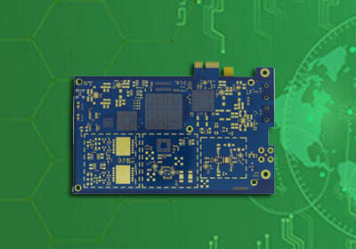


Model: 77G / 24G Millimeter Wave Radar PCB
Material: Rogers RO4835+S1000-2
Rogers RO3003G2 + ITEQ IT180 / Isola 370hr
DK: 3.48 / 3.0
Layer: 6 layer / 8 layer
Finished Thickness: 1.0-2.0mm
Copper Thickness: 0.5OZ/1OZ
Color: Green/Blue/Red
Min Trace/Space: 4mil/4mil
Surface Treatment: Immersion Gold / Silver
Through-hole treatment: link Plug
Application: Automobile Millimeter Wave Radar PCB
The main millimeter-wave radar uses 24G radar PCB and 77G radar PCB, and the millimeter-wave radar PCB is mainly used in automotive AI intelligent unmanned driving.
Millimeter-wave radar PCB has a wide application prospect. At present, iPCB adopts Rogers RO3003G2 + ITEQ IT180 to mass-produce 77GHz millimeter-wave radar PCB.
For different pcb radar designs of millimeter-wave radar sensors, a common feature is that ultra-low loss radar PCB material is needed to reduce circuit loss and increase antenna radiation. The radar PCB material is the key component in the design of radar sensors. Selecting the appropriate radar PCB material can ensure the stability and consistency of the millimeter-wave radar sensor.
How to Design the Performance of Radar PCB
First of all, the electrical characteristics of radar PCB materials are the primary factors in designing radar sensors and selecting radar PCB materials. Selecting radar PCB materials with stable dielectric constant and ultra-low loss is essential for the performance of the 77GHzmm-wave radar. The stable dielectric constant and loss can make the antenna receive and receive accurate phase, which can improve the antenna gain, scan angle or range, and improve the accuracy of radar detection and positioning. The stability of dielectric constant and loss property of PCB not only ensures the stability of different batches of materials but also ensures that the variation within the same PCB board is small and has very good stability.
The surface roughness of copper foil used in pcb radar material will affect the dielectric constant and loss of the circuit, and the thinner the material, the greater the surface roughness of copper foil will affect the circuit. The coarser the copper foil type, the greater the roughness change of itself, will also result in greater changes in dielectric constant and loss, and affect the phase characteristics of the circuit.
Secondly, the reliability of radar PCB material needs to be considered. The reliability of PCB materials not only refers to the high reliability of materials in PCB processing, affected by the processing process, through holes, copper foil binding force, etc. but also includes the long-term reliability of materials. Whether the electrical performance of radar PCB material remains stable with time and under different working conditions such as different temperatures or humidity is of great importance to the reliability of automotive radar sensors and the application of automotive ADAS systems.
For the PCB antenna design of 77 GHz radar sensor, it is necessary to consider selecting materials with stable dielectric constant and ultra-low loss. Smoother copper foil can further reduce circuit loss and dielectric constant tolerance change. At the same time, radar PCB materials should have reliable electrical and mechanical properties with time, temperature, humidity, and another external working environment.

Advantages of 77GHz band in automotive and industrial applications
RO3003G2 high-frequency radar PCB material
Rogers RO3003G2 high-frequency, ceramic-filled PTFE(Teflon) laminates are an extension of Rogers's 'industry-leading RO3003 solutions. RO3003G2 laminates are based on industry feedback to specifically address the next generation needs for Millimeter-wave automotive radar applications.
RO3003G2 laminate's combination of optimized resin and filler content provides a lower insertion loss, ideal for use in ADAS systems like adaptive cruise control, forward collision warning, and active brake or lane change assist.
RO3003G2 high-frequency radar PCB material Features
The dielectric constant of 3.00 at 10 GHz and 3.07 at 77 GHz
Very Low Profile (VLP) ED copper
Homogeneous construction incorporating VLP ED copper and reduced dielectric porosity
Enhanced Filler System
Benefits
Best in class performance for insertion loss
Minimize dielectric constant variation in finished PCB
Enable trend toward more small diameter vias
Global manufacturing footprint
Advantage 1: high range resolution and ranging accuracy
Compared with the ISM band with only 200MHz bandwidth in the 24GHz band, the SRR band in the 77GHz band can provide up to 4GHz scanning bandwidth, significantly improving the range resolution and accuracy. Among them, range resolution represents the ability of a radar sensor to separate two adjacent objects, and range accuracy represents the accuracy of measuring a single target.
Because the range resolution and accuracy are inversely proportional to the scanning bandwidth, the performance of a 77GHz radar sensor is better than that of a 24GHz radar, which is 20 times higher than that of a 24GHz radar. The range resolution of 77GHz radar is 4cm (the resolution of 24GHz radar is 75cm).
High range resolution can better separate objects (such as people standing near cars) and provide dense points to detect objects, to improve the environment modeling and object classification, which is very important for the development of advanced driving assistance algorithms and automatic driving functions.
In addition, the higher the resolution, the smaller the minimum distance of sensor recognition. Therefore, 77-81ghz radar has a significant advantage in applications requiring high accuracy, such as parking aid.
The 77GHz broadband has a high resolution, which can be used for industrial level sensors, so that the sensor can "measure to the last drop" of liquid level - to minimize the dead zone at the bottom of the water tank, as shown in the figure. Moreover, because the high resolution can improve the minimum measurement distance, when the water tank is full, the sensor can measure the liquid level at the top of the water tank.
Advantage 2: high-speed resolution and precision
The speed resolution and accuracy are inversely proportional to the radio frequency (RF) frequency. Therefore, the higher the frequency, the better the resolution and accuracy. Compared with the 24 GHz sensor, the 77 GHz sensor can reduce power consumption.
For parking aid applications, speed resolution and accuracy are crucial, because it is necessary to operate the vehicle accurately at a low speed when parking. Fig. 4 shows a representative FFT range velocity image of a point object at 1 m and depicts an improved resolution of a two-dimensional image obtained using 77 GHz.
In addition, recent studies have further improved pedestrian detection and advanced object classification algorithms by using radars with higher resolution and micro-Doppler signals. The improvement of speed measurement accuracy is conducive to industrial applications, but also to improve the current situation of traffic detection under the background of automatic vehicles.
Advantage 3: smaller size
One of the main advantages of higher RF frequency is that the sensor size can be smaller. For the same antenna field of view and gain, the size of the 77GHz antenna array can be reduced about three times in X and Y dimensions. This size reduction is very useful in the car, mainly reflected in the application around the car (including the door and trunk that need to install the proximity sensor) and in the car.
In the aspect of industrial fluid horizontal line sensing, higher RF frequency can provide a narrower beam for antennas and sensors of the same size. The narrow beam can reduce the unnecessary reflection from the side of the tank and the interference of other obstacles in the tank, to obtain more accurate measurement results. In addition, for the same beam width, the higher the RF frequency, the smaller the size of the sensor and the easier it to install.
Millimeter-wave pcb radar is the core technology of ADAS to improve safety and convenience. Target applications of millimeter-wave radar:
Reversing automatic emergency braking (R-AEB)
Front/rear cross-traffic assist function (FCTA/RCTA)
Parking Assist (PA)
Blind Spot Detection (BSD)
Cascade Imaging Radar (IMR)
Automatic emergency braking system (AEB)
Adaptive Cruise Control (ACC)
Lane Change Assist (LCA)
Radar 360° perception

Millimeter-wave radar in ADAS
What is the difference between 77G and 24G millimeter-wave radar?
The two frequency bands of 77G and 24G millimeter-wave radars are not much different in signal processing principles, but because the frequency determines the basic properties of electromagnetic waves, 77GHz millimeter waves, and 24GHz millimeter waves are suitable for different application tasks. One of the main disadvantages of radar is that the angular resolution is usually relatively low. Vehicle-mounted millimeter-wave radars generally use phased array antennas for angle measurement. The antenna design is directly related to the signal wavelength. On the one hand, to avoid the influence of grating lobes and electromagnetic coupling, the selection of the distance between the receiving antenna array elements will be based on half the wavelength. On the other hand, a shorter wavelength means that a smaller transmitting antenna can be used. Therefore, based on the above reasons, in the same volume, the 77GHz millimeter-wave radar can design more transceiver elements and form a larger aperture than the 24GHz millimeter-wave radar, thereby obtaining a narrower beam and improving the angle measurement accuracy.
This is very important for radar remote detection. This is because the arc length corresponding to the angular resolution unit in the polar coordinate system increases with the increase of the distance. For example, the arc length at 200 meters with a resolution of 5 degrees is about At 17 meters, it is wider than the average road, and the target cannot be distinguished in the horizontal direction. Therefore, the current 77GHz millimeter-wave radar is the mainstream solution for the forward long-range detection of cars, while the 24GHz millimeter-wave radar is mainly used for short-range detection of the rear and side of the car. The short-range 77G millimeter-wave radar is less used because the 24G millimeter-wave radar The technology is relatively mature, and the higher frequency hardware design will be more difficult and costly. According to different application backgrounds, different millimeter-wave radar parameters can be designed. For example, the forward long-range can use narrow-band signals to reduce interference, while the short-range bandwidth can be increased to improve the range resolution.
The 77GHzmm-wave radar system module is based on the design of FMCW radar. Most of them use complete single-chip solutions such as TI, Infineon, or NXP. The RF front-end, signal processing unit, and control unit are integrated into the chip, providing multiple signal transmission and reception channels. PCB board design varies from customer to antenna design, but there are three main ways.
a. Using ultra-low loss radar PCB material as the PCB carrier for the top antenna design, PCB antenna design usually uses microstrip patch antenna, and the layered second layer as the layer of the antenna and its feeder. Other laminated radar PCB materials are FR-4. This design is relatively simple, easy to process, and low cost. However, due to the thinner thickness (usually 0.127mm) of ultra-low loss radar PCB material, attention should be paid to the effect of copper foil roughness on loss and consistency. At the same time, the narrow feeder of radar PCB microstrip patch antenna requires attention to line width precision control.
b. Radar PCB design method uses dielectric integrated waveguide (SIW) circuit for antenna design. Radar PCB antenna is no longer a patch antenna. In addition to antennas, other radar PCB layers use FR-4 materials as the radar control and power layers as in a first way. Radar PCB board materials used in this SIW antenna design still use ultra-low loss radar PCB materials to reduce loss and increase antenna radiation. Thickness selection of materials usually increases the bandwidth with thicker radar PCB, but also reduces the influence of copper foil roughness. There are no other problems when processing narrow linewidth. However, the hole processing and positional accuracy of SIW need to be considered.
c. The design method is to design the stacked structure of multilayer PCB plates with ultra-low loss radar PCB materials. Depending on the requirements, it is possible that several layers use ultra-low loss radar PCB material, or that all layers use ultra-low loss radar PCB material. This design method greatly increases the flexibility of circuit design, increases the degree of integration, and further reduces the size of the radar module. However, the disadvantage is that the relative cost is high and the processing of radar PCB is relatively complex.

Three Radar PCB Design
The unique advantages of the 77GHzmm-wave radar sensor make it an indispensable part of automobile driving. Wider bandwidth and higher resolution 77GHz/79GHz radar sensors have gradually become the mainstream. For various radar sensor design schemes, the characteristics of radar PCB materials determine the performance of radar sensor antennas to a large extent.
Millimeter-wave radar PCB helps to drive autopilot, but they need multiple elements, including circuit materials that can provide stable performance for electronic devices and circuits with frequencies above 77 GHz. For example, in ADAS applications, circuit materials are required to support the design of transmission lines for microwave and millimeter-wave signals at 24,77 (or 79) GHz to minimize loss while providing consistent repeatability over a wide operating temperature range. Fortunately, Rogers offers this circuit material with the same performance required for ADAS applications from microwave to high-frequency millimeter wave bands.

millimeter-wave radar circuit
As a part of the electronic sensing protection of the vehicle ADAS system, the vehicle-borne radar system will be used together with other technologies. Radar systems transmit electromagnetic (EM) signals in the form of radio waves and receive reflected signals from radio waves from a target, such as another vehicle, which is usually multiple targets. The radar system can extract the information of the target, including its position, distance, relative velocity, and radar cross-section (RCS) from these reflected signals. The range (R) can be determined based on the speed of light (c) and the required round-trip time (τ) of the signal, which is the time when the radio wave travels from the radar energy source (radar transmitter) to the target and then back to the radar energy source. In vehicle-borne radar systems, the generation and reception of radar signals in PCB antenna. The value of R can be obtained by a simple mathematical formula, that is, the product of the speed of light and the round-trip transmission time from the radar signal source to the target and back to the radar source divided by 2: r = C τ / 2.

As part of ADAS active safety, the vehicle is equipped with a variety of sensors, including cameras, lidar, and radar systems
At present, various radars are used as part of ADAS applications. FMCW signal is widely used because of its effectiveness in measuring the velocity, range, and angle of multiple targets. Automotive radars sometimes use narrowband Nb and ultra-wideband UWB designs operating at 24GHz. The 24 GHz narrowband vehicle-borne radar occupies a 200 MHz range from 24.05 to 24.25 GHz, while the 24 GHz UWB radar has a total bandwidth of 5 GHz, ranging from 21.65 GHz to 26.65 GHz. Narrowband 24 GHz vehicle-borne radar system can provide effective short-range traffic target detection, and can be used for simple functions such as blind-spot detection. The UWB vehicle-borne radar system has been applied to higher range resolution functions, such as adaptive cruise control (ACC), forward collision warning (FCW), and automatic emergency braking (AEB).
However, as global mobile communications applications continue to consume the spectrum of "lower" frequencies (including 24 GHz accessories), the frequency of vehicle-borne radar systems becomes higher, and the available millimeter wave spectrum with shorter wavelengths becomes the choice, with frequencies of 77 and 79 GHz respectively. 24 GHz UWB vehicle-borne radar technology is no longer used in Japan. According to the schedules set by ETSI and FCC respectively, it will be phased out in Europe and the United States and will be replaced by higher frequency narrowband 77GHz and ultra-wideband 79ghz vehicular radar systems. 77GHz and 79GHz radar will be used as a functional module for autonomous driving in some form.
Radar is only one of the electronic technologies of future autopilot. Self-driving vehicles must be surrounded by different types of sensors, thus helping to continuously collect environmental data to protect the safety of cars and their passengers (one of which may be considered a driver). Self-driving vehicles will also rely on information processing called sensor fusion, simultaneous interpreting data collected from many different sensors into usable information and converting it into a safe and comfortable driving experience.
To accurately collect the data needed for the peripheral environment such as bicycles, self-driving vehicles, etc., many small multilayer printed circuit board antennas and other sensor circuits will need to use stable low loss circuit materials, such as Rogers ro3000, ro4000, and kappa Gamma 4385 laminate with the performance and stability required by the circuit at RF to millimeter-wave frequencies.
The size of the circuit decreases with increasing frequency, especially at 77 and 79 GHz, because these signal wavelengths are very small. All kinds of circuit transmission lines working in this frequency band, including microstrip line, stripline, and coplanar waveguide (CPW) circuit, require very good consistency and predictability of materials due to the small size of the circuit, such as ro3003 Gamma And ro4830 Gamma Laminate. High-frequency circuit materials, such as the Rogers ro3003 laminate, remain particularly consistent in different circuits and changing environments, with particularly good DK performance, while having the low loss factor (DF) or loss required at millimeter-wave frequencies (Fig. 5). Ro4830 thermosetting laminate is very suitable for price-sensitive millimeter-wave applications. It is also a reliable and low-cost alternative to traditional PTFE-based laminates. The dielectric constant of ro4830 laminate is 3.2 at 77 GHz. LoPro? Reverse copper foil technology helps optimize the insertion loss of ro4830 laminates at 77GHz with an insertion loss value of 2.2db per inch.
The excellent mechanical and electrical performance level of ro3000 and ro4000 circuit materials can be compared with that of ro4400 Gamma The bonding materials are combined and perform very well and consistently with low loss circuit characteristics at 79 GHz. These key circuit materials will provide repeatable and reliable electrical performance and enable the sensor to obtain reliable data for the onboard processor of the autopilot vehicle, to ensure the safe driving of the vehicle.
IPCB circuit is a professional manufacturer of millimeter-wave radar PCB. At present, IPCB has matured and mass-produced 24G millimeter-wave radar PCB and 77G millimeter-wave PCB. If you need to radar PCB manufacturing, please contact ipcb circuit.
Model: 77G / 24G Millimeter Wave Radar PCB
Material: Rogers RO4835+S1000-2
Rogers RO3003G2 + ITEQ IT180 / Isola 370hr
DK: 3.48 / 3.0
Layer: 6 layer / 8 layer
Finished Thickness: 1.0-2.0mm
Copper Thickness: 0.5OZ/1OZ
Color: Green/Blue/Red
Min Trace/Space: 4mil/4mil
Surface Treatment: Immersion Gold / Silver
Through-hole treatment: link Plug
Application: Automobile Millimeter Wave Radar PCB
For PCB technical problems, iPCB knowledgeable support team is here to help you with every step. You can also request PCB quotation here. Please contact E-mail sales@ipcb.com
We will respond very quickly.


