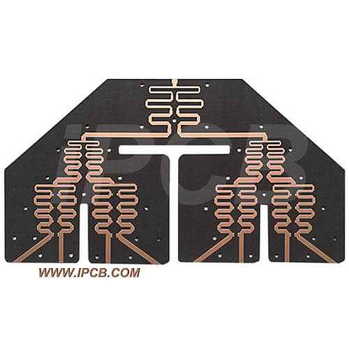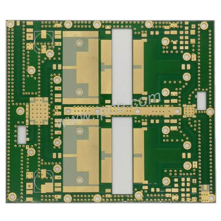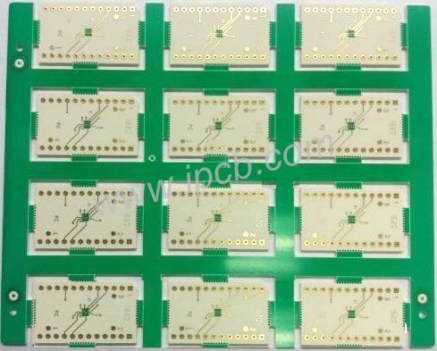


Product Name: Radar PCB
Material: Teflon / Ceramic PCB
Quality standard: IPC-6012
Dielectric constant: 2.0-16
Layers: 1 Layer - 70 layer
Thickness: 0.254mm - 6.0mm
Copper thickness: H/H-1OZ
Surface technology: Silver(Can choose Gold or OSP)
Application: Communication radar PCB, detection radar PCB
Radar PCB is a PCB substrate used in radar, commonly used in communication radar PCB, detection radar PCB, millimeter-wave radar, etc. At present, the millimeter-wave radar used in ADAS is developing very rapidly. For the millimeter-wave radar of ADAS, please click Millimeter-wave radar.
Radar PCB requires high-frequency PCB materials. DK and DF of this kind of high-frequency PCB materials need special manufacturing control, IPCB company uses DK 2-16 high-frequency PCB materials to manufacture radar PCB, such as Teflon PCB materials, ceramic PCB materials, and hydrocarbon PCB materials.
Radar radiates electromagnetic waves. Radio waves are emitted through the radar's antenna and are reflected by obstacles in front. Radar is a magical electrical device that measures the distance between objects blocked by electromagnetic wave travel time.
A primary radar system consists of a transmitter that generates electromagnetic waves, an antenna that directs electromagnetic waves to radiate and receive return energy, a receiver that amplifies the return signal, and a display that expresses the target's location. The radar emits a tiny part of the electromagnetic wave irradiated on the target, scattering in all directions.
The radar receives the backscattered signal through the antenna. Then the radar transmits this part of the energy to the receiver, identifies the existence of the target according to the symbols in the receiver, and measures its position and velocity. The radar estimates the target's distance according to the time required for the transmitted electromagnetic wave to reach the reflector and return to the receiving antenna. The direction of the antenna determines the angular position of the target object. Radar has been widely used in military, aviation, navigation, meteorology, and other departments because it can quickly and accurately determine the target's spatial position.
Radar is divided into military and civil types.
1. Air Intelligence Radar. Used to search, monitor, and identify air targets. It includes air-warning radar, guidance radar, and target-indicating radar, as well as low-altitude radar designed to detect low-altitude and ultra-low-altitude penetration targets.
2. Marine warning radar. Radar used to detect surface targets is usually mounted on various surface vessels or coasts and islands.
Classification of Radars
Classify by function: warning radar, guidance radar, artillery target radar, airborne fire control radar, altitude measuring radar, blind landing radar, terrain avoidance radar, terrain tracking radar, imaging radar, meteorological radar, etc.
Classified by working system: conical scanning radar, monopulse radar, passive phased array radar, active phased array radar, pulse compression radar, frequency-agile radar, MTI radar, MTD radar, PDradar, synthetic aperture radar, noise radar, shock radar, bistatic/multi-static radar, sky/ground wave over-range radar, etc.
Classify by working wavelength: meter-wave radar, decimeter-wave radar, centimeter-wave radar, millimeter-wave radar, lidar/infrared radar.
It is classified according to the coordinate parameters of the measuring target: two-coordinate radar, three-coordinate radar, velocity radar, altitude radar, guidance radar, etc.

The antenna array of phased array radar is also composed of many radiating units and receiving units (called array units). The number of units is related to the function of radar, which can range from hundreds to tens of thousands. These elements are regularly arranged on the plane to form an array antenna. By using the principle of electromagnetic wave coherence and controlling the phase of the current fed to each radiation unit by computer, the direction of the beam can be changed for scanning, so it is called electrical scanning. The radiation unit sends the received echo signal to the host to complete the radar search, tracking, and measurement of the target. In addition to the antenna oscillator, each antenna unit also has necessary devices such as a phase shifter. Different oscillators can be fed into different phase currents through phase shifters, so as to radiate beams with different directivity in space. The more elements of the antenna, the more possible orientations of the beam in space. The working basis of this radar is the phase controllable array antenna, which is named "phased array".
Phased array radar can be divided into two types. First, passive radar, PESA for short, is a kind of radar with relatively low technical performance. It has developed maturely in the 1980s and is applied to ships and small and medium-sized aircraft. The second is radar technology with better performance, good development prospects, and higher technical performance than the first. This technology was not applied until the late 1990s and began to be applied to fighter and shipborne systems. This technology is "active (AESA)".
Phased array radar widely uses electronic positioning technology in modern war, and has carried out in-depth exploration. In the military, it is a great demand for long-range precision attacks in the sea and air, which requires the deeper application of positioning technology.
Range measurement: the range is commonplace for testing and identifying weapons and equipment, and can also test and launch spacecraft. The measurement of the shooting range is based on the test and serves the application.
1. Missile range. The missile range is divided into two parts, namely, the upper range and the lower range. The upper range is also called the launch area or the head area, and the lower range is also called the reentry area or the landing area and the landing area. The upper shooting range of the missile is the place where the missile is launched. Its main task is to monitor whether the flight orbit of the missile is the preset orbit, which is the basis for confirming the safety of the shooting range, and to provide data for various physical phenomena of the new missile in the flight process. The lower range of missiles is mainly a place to measure and identify the characteristics of missile targets and anti-missile weapon systems.
2. Space shooting range. Strategic missiles are the basis of space launch vehicles. Therefore, the early missile shooting range is still a proud spacecraft launch point.
3. Conventional shooting range. Conventional shooting range can be divided into conventional weapon shooting range and electronic shooting range. Among them, the conventional weapon shooting range has always been the focus of vigorous development in various countries. It has the characteristics of great power, high precision, multiple functions, good efficiency, and low cost.

Radar PCB design
Radar PCB combines various digital and mixed-signal technologies, so PCB layout and PCB design become more challenging, especially when RF and microwave are mixed for sub-components. Whether you cooperate with us, with other radar PCB suppliers, or design your own radar PCB, you need to consider some matters.
The range of radar frequencies is usually very high, but designs above 1GHz are usually regarded as PCB radar. If your PCB operating frequency exceeds 1GHz, you are in the range of PCB radar. The PCB radar is using very high-frequency microwave signals.
Why is it so difficult to design RF and radar PCB?
There are many problems in the design of radar PCB, which may have a serious impact on quality and productivity. For example, when embedding the RF circuit of one designer into the PCB of other designers, they often use different design formats, so the efficiency must be greatly reduced. In addition, designers are often forced to make changes in the design in order to cooperate with the use of RF circuits. Because the simulation is often carried out in the RF circuit, rather than in the context of the whole radar PCB, the significant impact of the radar circuit board on the RF circuit may be omitted, and vice versa.
With the increasing content of radar PCB, PCB designers and engineers realize that in order to improve productivity and product quality, it is best for them to solve RF design challenges by themselves in their own design tools. Unfortunately, most desktop radar PCB design tools do not help them simplify this task.
For example, once the required electrical performance is achieved after modeling the radar PCB with an RF simulator, The simulator will produce the copper foil shape of the circuit (usually in DXF format) in order to import it into PCB design tools. This process often brings some troubles to designers. For example, they can't convert it to copper foil shape because they can't convert the DXF file correctly. In this case, designers need to manually import DXF files, which may lead to human errors and errors in shape and size RF circuit failure.
The challenges faced by radar PCB designers or engineers when trying to design PCB layout for RF and microwave circuits are far more than the above.
Why do you need to choose the right radar PCB manufacturer?
Radar PCB is very sensitive to noise, impedance, electromagnetic. High-quality radar PCB manufacturers focus on eliminating any influencing factors in the manufacturing process. Poor quality radar PCB is not expected to last long, which is why choosing a perfect radar PCB manufacturer can change your product experience.
Why choose IPCB for radar PCB manufacturing?
IPCB has more than ten years of experience in radar PCB manufacturing, and IPCB professionals have professional knowledge of PCB manufacturing based on radar PCB materials. IPCB has been committed to providing radar PCB manufacturing for various products around the world. IPCB provides satisfactory services to customers and establishes long-term cooperative relations with customers.
Product Name: Radar PCB
Material: Teflon / Ceramic PCB
Quality standard: IPC-6012
Dielectric constant: 2.0-16
Layers: 1 Layer - 70 layer
Thickness: 0.254mm - 6.0mm
Copper thickness: H/H-1OZ
Surface technology: Silver(Can choose Gold or OSP)
Application: Communication radar PCB, detection radar PCB
For PCB technical problems, iPCB knowledgeable support team is here to help you with every step. You can also request PCB quotation here. Please contact E-mail sales@ipcb.com
We will respond very quickly.